This thread has been locked.

If you have a related question, please click the "Ask a related question" button in the top right corner. The newly created question will be automatically linked to this question.

RTOS/SW-EK-TM4C1294XL: SPI initialise on BoosterPack 1

Part Number: SW-EK-TM4C1294XL
Other Parts Discussed in Thread: EK-TM4C1294XL

Tool/software: TI-RTOS

Hello there, 

im trying to initialise the SPI BUS at BoosterPack 1 to write/read data to a sensor.

But i became  by initializing the SPI bus an error.

Below is my code:

I will appreciate any answers or ideas.

Thank you i forward! 

void setup_SPIBus() 
{

Board_initSPI();

SysCtlPeripheralEnable(SYSCTL_PERIPH_GPIOP);
GPIOPinTypeGPIOOutput(GPIO_PORTP_BASE, GPIO_PIN_5);
SSIClockSourceSet(SSI3_BASE, SSI_CLOCK_SYSTEM);

SSIConfigSetExpClk(SSI3_BASE, ui32SysClock, SSI_FRF_MOTO_MODE_0, SSI_MODE_MASTER, 10000000, 16);
SSIEnable(SSI3_BASE);

}

  • If you are getting a hard fault, it is often because you are accessing a peripheral that has not been enabled. See Issue #7 in this post for how to debug the cause of a hard fault: e2e.ti.com/.../374640
  • It is noted that besides,  "Failing to enable SSI3"

    • None of the SSI3 pins have been,  "Pin Typed or Pin Configured"
    • it is unknown (by me) how the necessary SSI3 "Set-Up/Config" is divided between the RTOS & the (normal) API code
    • you note an "error" - (some) description of that error (always) proves helpful...

  • Firstly i want You to thank for the help!

    My situation is es follow:

    on boosterpack 1 of lanchpad I have connected an microbus modul 

    on mikrobus modul I have connected an sensor ( rotary click encoder )

    1) am I right with ssi2 or i need to initialize ssi3 ?

    2) the problem is at Bolt line: by debug the curser jump not  to the next source line 

    void setup_SPIBus()
    {

    //LaunchPad Workshop Seite 193

    Board_initSPI();

    SysCtlPeripheralEnable(SYSCTL_PERIPH_GPIOP);
    GPIOPinTypeGPIOOutput(GPIO_PORTP_BASE, GPIO_PIN_5);
    // SSIClockSourceSet(SSI2_BASE, SSI_CLOCK_SYSTEM);
    SSIClockSourceSet(SSI3_BASE, SSI_CLOCK_SYSTEM);

    SSIConfigSetExpClk(SSI3_BASE, ui32SysClock, SSI_FRF_MOTO_MODE_0, SSI_MODE_MASTER, 10000000, 16);

    SSIEnable(SSI2_BASE);
    }


  • Is this the Microbus module that you have on boosterpack 1 of the EK-TM4C1294XL launcpad?
    download.mikroe.com/.../click-booster-pack-manual-v100.pdf

    If yes, then :
    SCL is PD3, SSI2CLK
    SDO is PD1, SSI2XDAT0
    SDI is PD0, SSI2XDAT1

    So I think you should use SSI2, not SSI3.
  • Hi Bob, 

    Thanky very much for your help!

    The link of the module you have inserted above ist right !

    now SPI init works fine. 

    But now i am trying to read the state of rotate button and click button of rotary click module over mikro module and i am having some trouble.

    How can i do it , over GPIO#s,  interrupt or SPI read/write ?

    Once more thanks for your support!


  • Erion Erion said:
    Im trying to initialize the SPI BUS at BoosterPack 1 to write/read data to a sensor.

    The above quote flows from your first sentence - w/in your first post - this thread.       Yet now you appear to, "Question the use of SPI."       Is not that determination, "Yours to make" - and if at all unsure - should not (that) outside vendor receive your questioning?

    From experience - most such "sensors" provide their signals via a serial bus (SPI or I2C, usually) and it would be unusual for a "GPIO" to be "in play" for (other) than a device "Chip Select."

  • Hello Erion,

    Unfortunately I cannot answer your question because I have no idea which encoder you are using or how it connects to the pins of the EK-TM4C1294XL board. Simple rotary switch encoders I have seen have an A and B output that generate out-of-phase "square" waves as the switch is rotated. By examining the relationship between the two signals you can determine which way the switch is rotated. By counting pulses you can determine the angle of the rotary switch. Simple implementations may use just GPIOs and software de-bounce the signals. If the switch already has a de-bounce circuit, you can use interrupts to reduce the CPU overhead.

  • Hello Bob, cb1_mobile  and the others, 

    fisrt thanks a lot for your comments and infos!

    below i will try  to describe you my problem more and the lessclearly to get more exactly infos from you :

    My Stituation:

    I have  a lunchpad EK-TM4C1294XL and there is mounted  at Boosterpack 1 of Lunchpad a  Rotary Encoder over a Microbus. (both from microe.com) 

    Unfortunately  in their homepage is no information about how it works with a TI Lunchpad. the only Information that I can find is in the manual:


    It communicates with the target board through mikroBUS™  SPI lines (CS, SCK, MISO, MOSI), and three

    additional lines for outputting the Encoder info: ENCB OUT, ENCA OUT and SW (in place of the standard AN, RST and INT pins, respectively).

    I think this encoder works exactly as Bob describes above.  So Pulse Signals of rotate Button (in orginal docu describes as  A and B ) could be readed only over SPI protokoll because the both Signals A and B of rotary encoder  are included in the SPI lines. .....have i maybe understood this wrong ? 

    To arrive this i have only to work with this GPIOs:

    CS - SPI Chip Select line //high

    SCK - SPI Clock line 

    MISO - SPI Slave Output line //output

    MOSI - SPI Slave Input line //output

    Below is my code but it does work as i want to:

    #include <stdbool.h>
    #include <stdint.h>
    #include <inc/hw_memmap.h>
    
    /* XDCtools Header files */
    #include <xdc/std.h>
    #include <xdc/cfg/global.h>
    #include <xdc/runtime/System.h>
    #include <xdc/runtime/Error.h>
    #include <xdc/runtime/Memory.h>
    
    /* BIOS Header files */
    #include <ti/sysbios/BIOS.h>
    #include <ti/sysbios/knl/Task.h>
    
    /* Currently unused RTOS headers that are needed
    * for advanced features like IPC. */
    #include <ti/sysbios/knl/Semaphore.h>
    #include <ti/sysbios/knl/Mailbox.h>
    #include <ti/sysbios/knl/Event.h>
    #include <ti/sysbios/hal/Timer.h>
    #include <ti/drivers/SPI.h>
    
    /* Driverlib headers */
    #include <driverlib/gpio.h>
    
    /* Board Header files */
    #include <Board.h>
    #include <EK_TM4C1294XL.h>
    
    /* Application headers */
    #include <Blink_Task.h>
    #include <UART_Task.h>
    #include <TCPEcho_Task.h>
    
    #include <driverlib/sysctl.h>
    #include <driverlib/pin_map.h>
    #include <driverlib/ssi.h>
    #include "BSPIBus.h"
    #include "7x5font.h"
    
    const unsigned short tokenSeg_1[]={
        0x7E, //0
        0x0A, //1
        0xB6, //2
        0x9E, //3
        0xCA, //4
        0xDC, //5
        0xFC, //6
        0x0E, //7
        0xFE, //8
        0xDE, //9
        0xEE, //A    10
        0xFE, //B
        0x74, //C
        0xBA, //D
        0xF4, //E
        0xE4, //F    15
        0x01, //'.'  16
        0xB8, //a    17
        0xE8, //b
        0xB0, //c
        0xBA, //d    20
    };
    
    uint32_t ui32SysClock;
    int i;
    uint32_t data = 0;
    uint32_t *pui32Data;
    uint8_t ui8PinData=1;
    uint32_t messungPin1;// = LOW;
    uint32_t messungPin1Alt;// = LOW;
    int encoderWert = 0;
    int32_t i32Val_A;
    int32_t i32Val_B;
    uint32_t status;
    char *pcChars = "SSI Master send data.";
    int32_t i32Idx;
    
    int main(void)
    {
    
        ui32SysClock = Board_initGeneral(120 * 1000 * 1000);
    
        ui32SysClock = SysCtlClockFreqSet((SYSCTL_XTAL_25MHZ | SYSCTL_OSC_MAIN | SYSCTL_USE_PLL |
                SYSCTL_CFG_VCO_480), 120000000);
    
        //***************************************************************
        //System Setup
        //***************************************************************
    
        //LaunchPad Workshop Page 193
        //Initialize SPI Bus********************************************
        Board_initSPI();
    
        // Enable the SSI0 peripheral
        SysCtlPeripheralEnable(SYSCTL_PERIPH_SSI0);
        while(!SysCtlPeripheralReady(SYSCTL_PERIPH_SSI0))
        {
        }
    
        // Configure the SSI Bus as Master
        SSIConfigSetExpClk(SSI2_BASE, ui32SysClock, SSI_FRF_MOTO_MODE_0,
                              SSI_MODE_MASTER, 10000000, 8);
    
        // Enable the SSI2 module
        SSIEnable(SSI2_BASE);
    
        //Initialize Lunchpade GPIO's********************************************
    
        //Enable GPIOP Peripheral
        SysCtlPeripheralEnable(SYSCTL_PERIPH_GPIOD);
        //SysCtlPeripheralEnable(SYSCTL_PERIPH_GPIOP);    // enable port P for CS 74HC595
    
        // Wait for the GPIOD module to be ready.
        while(!SysCtlPeripheralReady(SYSCTL_PERIPH_GPIOD))
        {
        }
    
        // Configure the GPIO's
        GPIOPinConfigure(GPIO_PD3_SSI2CLK);     //SCL is PD3, SSI2CLK
        GPIOPinConfigure(GPIO_PD0_SSI2XDAT1);   //SDI is PD0, SSI2XDAT1
        GPIOPinConfigure(GPIO_PD1_SSI2XDAT0);   //SDO is PD1, SSI2XDAT1
        GPIOPinConfigure(GPIO_PD2_SSI2FSS);     // ~CS
    
        // Configure the GPIO's as INPUT or Output
        GPIOPinTypeGPIOInput(GPIO_PORTD_BASE, GPIO_PD0_SSI2XDAT1); //INPUT SSI2XDAT1
        GPIOPinTypeGPIOOutput(GPIO_PORTD_BASE, GPIO_PD1_SSI2XDAT0); //OUPUT SSI2XDAT1
    
        // set chip select (LATCH) HIGH
        GPIOPinWrite(GPIO_PORTP_BASE, GPIO_PD2_SSI2FSS, 0xFF);
    
        // Enable SSI2 Clock System
        //SSIClockSourceSet(SSI2_BASE, SSI_CLOCK_SYSTEM);
    
        //***************************************************************
        // System Run Send and Read Data
        //***************************************************************
    
    //    status = GPIOPinRead(GPIO_PORTD_BASE, GPIO_PD2_SSI2FSS);
    //    SSIDataPut(SSI2_BASE, 0x0F);
    //    SSIDataGet(SSI2_BASE, &data);
    
        // set chip select (LATCH) LOW
        GPIOPinWrite(GPIO_PORTP_BASE, GPIO_PD2_SSI2FSS, 0x00);
    //    status = GPIOPinRead(GPIO_PORTD_BASE, GPIO_PD2_SSI2FSS);
    
    //    while(1)
    //    {
            i32Idx = 0;
            while(pcChars[i32Idx])
            {
                SSIDataPut(SSI0_BASE, pcChars[i32Idx]);
                i32Idx++;
            }
    
    //    }
    
    }


  • Erion Erion said:

    It communicates with the target board through mikroBUS™  SPI lines (CS, SCK, MISO, MOSI), and three additional lines for outputting the Encoder info: ENCB OUT, ENCA OUT and SW (in place of the standard AN, RST and INT pins, respectively).

    My friend - "feel your pain" - yet you've ventured "deep into the swamp" - and stand now in "QuickSand!"     (Never good!)

    By "my read" of your quote (ABOVE) those 3 Encoder Signals are NOT part of the SPI interface!     I base that conclusion upon the clause "three additional lines for outputting the Encoder..."    Now "IF" those 3 Encoder signals were routed via SPI - what would be the point (justification) - for providing them "additionally & separately" - as well?    That makes NO SENSE - don't you agree?

    Erion Erion said:
    So Pulse Signals of rotate Button (in orginal docu describes as  A and B ) could be readed only over SPI protokoll because the both Signals A and B of rotary encoder  are included in the SPI lines. .....have i maybe understood this wrong ? 

    In my opinion - as I've noted in response to "Quote 1" those encoder signals are ADDITIONAL to the SPI signals - they are thus (most likely) separate!    Again I ask you to consider - if they are provided as "SPI signals" - why are they supplied "additionally" as well?    (Now I CAN think of one reason - the conversion process from Encoder output into SPI format - "Does require time - thus slowing response!")

    What then "Can you Do?"       And what, "Should you Do?"

    We know nothing of the encoder!     Can you rotate it by hand - so that "some" output is achieved?     You may then confirm that the encoder signals - indeed - appear (additionally and separately) AWAY FROM the SPI signals!    (note: this requires a scope - so that you can "see" the encoder output signals)    By hand-rotating the encoder - you can confirm - (both) the presence & functionality - of those 3 additional lines.    Upon that confirmation - can you monitor the SPI signals from your "sensor" - and see how those signals behave - as you rotate the encoder?

    I hope the above is detailed enough - and sufficiently clear - to guide & assist.    (always my goal)    

    I'm unable to understand how you came to the conclusion that "SPI" is required to, "Attach to this Encoder."     Your MCU includes a "3 pin, QEI Module" - which is intended for, "Exactly that role!"    And - unless the QEI pins and the SPI pins "SHARE" the same "pin locations" w/in your MCU - the SPI aspect seems, "FAR MORE NEGATIVE THAN HELPFUL!"    

    To address your issue in (another) way - "From where did you determine that, "SPI should connect to your Encoder?"    Note too that (most) encoders provide 3 signal outputs (only)!     Thus "SPI" usage - in which "two-way" signal communication is EXPECTED - seems unlikely.    (or at least - greatly limited.)

    You may note that my firm & I are BIG fans of "KISS."    (KISS = simple, measurable, one challenge at a time!)    

    Your use of the RTOS  AND  BoosterPack - to my mind - gravely COMPLICATES your attempt to "Atttach to a simple, 3 wire encoder" - which should simply, easily & directly CONNECT to your MCU board - ALONE!    (again - to the MCU's QEI inputs - NOT to SPI.)    

    This FREES you (and your hapless helpers) from the MANY COMPLICATIONS (all unwanted) introduced by RTOS and Boosterpack!      (really - only confusion has been "boosted!")

  • Hello cb1_mobile, 

    Thanks a lot for your gold answer ! 

    My friend - "feel your pain" - yet you've ventured "deep into the swamp" - and stand now in "QuickSand!"     (Never good!)


    I continue te be in a dark deep swamp ! 

    Hier is a link of my rotary encoder module from mikroe.com:

    rotary g click 

    As you see in the frame there is not clearly declare how the rotary pins comunicate with the rest of the circuit

    or am I not able to understadant it????? maybe ?? !!!

    Frame: ____https://download.mikroe.com/documents/add-on-boards/click/rotary-g/rotary-g-click-manual-v100.pdf

    I don't unfortunatelly understand the meaning of this part:

    (in place of the standard AN, RST and INT pins, respectively).


    I red your answer and i now i am trying this one:

    #include <stdbool.h>
    #include <stdint.h>
    #include <inc/hw_memmap.h>
    
    /* XDCtools Header files */
    #include <xdc/std.h>
    #include <xdc/cfg/global.h>
    #include <xdc/runtime/System.h>
    #include <xdc/runtime/Error.h>
    #include <xdc/runtime/Memory.h>
    
    /* BIOS Header files */
    #include <ti/sysbios/BIOS.h>
    #include <ti/sysbios/knl/Task.h>
    
    /* Currently unused RTOS headers that are needed
    * for advanced features like IPC. */
    #include <ti/sysbios/knl/Semaphore.h>
    #include <ti/sysbios/knl/Mailbox.h>
    #include <ti/sysbios/knl/Event.h>
    #include <ti/sysbios/hal/Timer.h>
    #include <ti/drivers/SPI.h>
    
    /* Driverlib headers */
    #include <driverlib/gpio.h>
    
    /* Board Header files */
    #include <Board.h>
    #include <EK_TM4C1294XL.h>
    
    /* Application headers */
    #include <Blink_Task.h>
    #include <UART_Task.h>
    #include <TCPEcho_Task.h>
    
    #include <driverlib/sysctl.h>
    #include <driverlib/pin_map.h>
    #include <driverlib/ssi.h>
    #include "BSPIBus.h"
    #include "7x5font.h"
    #include <driverlib/qei.h>
    #include <driverlib/qei.c>
    
    #include <stdbool.h>
    #include <inc/hw_gpio.h>
    #include <inc/hw_types.h>
    #include <inc/hw_ints.h>


    volatile int qeiPosition;
    
    
    int main(void)
    {
    
        // Set the clocking to run directly from the crystal.
        SysCtlClockSet(SYSCTL_SYSDIV_4|SYSCTL_USE_PLL|SYSCTL_XTAL_16MHZ|SYSCTL_OSC_MAIN);
    
        // Enable QEI Peripherals
        SysCtlPeripheralEnable(SYSCTL_PERIPH_GPIOD);
        SysCtlPeripheralEnable(SYSCTL_PERIPH_QEI0);
    
        //Unlock GPIOD7 - Like PF0 its used for NMI - Without this step it doesn't work
        HWREG(GPIO_PORTD_BASE + GPIO_O_LOCK) = GPIO_LOCK_KEY; 
        HWREG(GPIO_PORTD_BASE + GPIO_O_CR) |= 0x80;
        HWREG(GPIO_PORTD_BASE + GPIO_O_LOCK) = 0;
    
        //Set Pins to be PHA0 and PHB0
        //GPIOPinConfigure(GPIO_PD3_IDX0);
        GPIOPinConfigure(GPIO_PD6_PHA0);
        GPIOPinConfigure(GPIO_PD7_PHB0);
    
        //Set GPIO pins for QEI. PhA0 -> PD6, PhB0 ->PD7. I believe this sets the pull up and makes them inputs
        GPIOPinTypeQEI(GPIO_PORTD_BASE, GPIO_PIN_6 |  GPIO_PIN_7 | GPIO_PIN_3);
    
        //DISable peripheral and int before configuration
        QEIDisable(QEI0_BASE);
        QEIIntDisable(QEI0_BASE,QEI_INTERROR | QEI_INTDIR | QEI_INTTIMER | QEI_INTINDEX);
    
        // Configure quadrature encoder, use an arbitrary top limit of 1000
        QEIConfigure(QEI0_BASE, (QEI_CONFIG_CAPTURE_A_B  | QEI_CONFIG_NO_RESET  | QEI_CONFIG_QUADRATURE | QEI_CONFIG_NO_SWAP), 1000);
    
        // Enable the quadrature encoder.
        QEIEnable(QEI0_BASE);
    
        //Set position to a middle value so we can see if things are working
        QEIPositionSet(QEI0_BASE, 500);
    
        //Add qeiPosition as a watch expression to see the value inc/dec
        while (1) //This is the main loop of the program
        {
            qeiPosition = QEIPositionGet(QEI0_BASE);
            SysCtlDelay (1000);
        }
    }
    

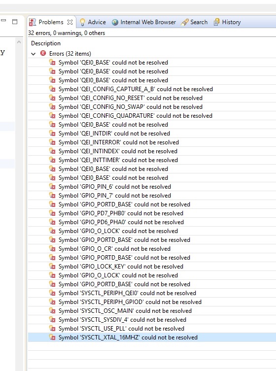
    But by compiling i got this error:

    Description Resource Path Location Type
    #20 identifier "GPIO_PD6_PHA0" is undefined main.c /Copy of rtos_blinky line 84 C/C++ Problem
    #20 identifier "GPIO_PD7_PHB0" is undefined main.c /Copy of rtos_blinky line 85 C/C++ Problem
    gmake: *** [main.obj] Error 1 Copy of rtos_blinky C/C++ Problem
    gmake: Target 'all' not remade because of errors. Copy of rtos_blinky C/C++ Problem
    Symbol 'GPIO_PD6_PHA0' could not be resolved main.c /Copy of rtos_blinky line 84 Semantic Error
    Symbol 'GPIO_PD7_PHB0' could not be resolved main.c /Copy of rtos_blinky line 85 Semantic Error

    :

  • Thank you - yours is a very quick - yet highly detailed response. Both much appreciated.

    What to say? Following "KISS" - can we "bypass" the RTOS - at least until we get your encoder to perform? (Firm/I would never use a "single vendor's offering" - such proves far too limiting!)

    I did note your code line: "#include <driverlib/qei.c>" It is "bad practice" to include the .c file! (.h should prove sufficient)

    I would expect that "qei.h and/or pin_map.h" to include (both) of your "GPIO_PD6_PHA0 & PHB0" definitions. It may be that the RTOS is causing them to be rejected. You may search for the presence of each of those identifiers - even a "general Windows Search should work."

    Try that - and report.     And perhaps explain why you "feel the need" for the RTOS.     As time "frees up" later today (we work on Sunday!) I'll review your encoder spec - thanks for linking...

  • Thank you for your help.

    i do not exatly now waht i have done wrong but by compiling the project i bekam those failurs:

  • Well that's not good!

    May I suggest that (temporarily) you AVOID the RTOS - find a simple, "Vendor supplied Project" - and load "just that!"     The "Vendor Supplied Projects" enjoy great success - and MANAGE "all of the many difficult/demanding Set-Ups & Configs" - which "over-challenge" we mortals!"      Those difficult Set-Ups/Configs are the "Main Suspects" in your recent,  "Error Invasion!"

    The simple Vendor Supplied Project should compile w/out errors - at that time add "small pieces/sections" of YOUR code.      Again - small sections - one at a time (then regularly confirming that your (expanding) code remains "error-free!")       (so that the "completed" code loads w/out dreaded errors.)

    I would also suggest that you remove the connection to any booster board (again this is temporary) so that we may minimize the chance of "interference brought on by, "too much - too soon."     Complexity - brought about by extra boards AND an RTOS - has NOT succeeded (has it?)       My approach is to follow KISS - and  SIMPLIFY as much as possible.

    When you've achieved this - post again & we'll (together) try to "escape from the swamp..."

  • thanks a lot for your Help. 

    Now i can the code compile and debug it on the board.

    The problem was that my Board TM4C1294XL  use Port L  and not port D ( the port D will be used by board TM4C123 ) to comunicate with QEI. 

    That is described here in manual  page 1750. (!!!)

    So now i compile th code and transfere it to the board and debug it. 

    Now the question is how can i see by debunging the two signals (A and B) of my Encoder ?! 

    Thank you!

  • While it is good to learn that your code (now) compiled - I cannot (even begin) to believe that your  "change from Port_L to Port_D" (ALONE)  - caused the  "Elimination of ALL of your past Errors!"

    Others are sure to come across your thread - and we should "offer them a "Path to Success too" - and I don't believe "we've (yet) done that!"     (that's most worthwhile - don't you agree?)

    May I ask - what ELSE - beyond the "change of two Ports" - did you change - to enable a successful compile?     Have you followed (any) of my "KISS" (i.e. Simplify) guidance?     Firm/I "Design & Diagnose such issues, For a living" - thus we have some record of success - and attribute most of that to such, "Quest for Simplification!"     (insuring Full, highly ORGANIZED & FOCUSED ATTENTION!)     (Not possible when "too many balls are "in the air.")   (i.e. "here")

    You ask now, "How to debug Encoder signals "A & B?"    

    • Have you access to a scope?    
    • The encoder spec sheet should reveal a timing diagram - rotating your encoder should enable you to monitor those "A & B" outputs
    • If they appear to specification - then you must insure that they (indeed) reach the proper pins w/in your MCU
    • AND - that no other (possibly offending) connections are present.     (which explains WHY I've suggested that you,  "abandon the booster board - for now.")

    Under  TWare/examples/peripherals/ check if your version includes any  QEI code examples.    (mine has none)    If none reveal - Carefully read the QEI chapter w/in the "Peripheral Driver Library User Guide" - which is a terrific document - indeed HAS a QEI example - and details each/every "QEI Function" - exactly what you require...

    Allez!