This thread has been locked.

If you have a related question, please click the "Ask a related question" button in the top right corner. The newly created question will be automatically linked to this question.

TM4C1294NCPDT: Using STM LIS3DSH Accelerometer w/ TM4C

Part Number: TM4C1294NCPDT

I'm using an STM LIS3DSH accelerometer with my TM4C1294 dev board communicating with I2C module 2.  The LIS3DSH has a "who am I" register where it returns a specific byte value when queried.  I had this returning the proper byte when doing the communication using the standard peripheral library, however when moving the code to a function, it no longer returned the proper byte value, so I figured I had some timing/configuration issue with my I2C communication.

After much fiddling and unable to get things to work, I decided to go down another route: Bypass the standard peripheral library and read/write directly from/to registers to see if I could get more insight into the problem.  I've done this by following the "Initialization and Configuration" for "Configure the I2C Module to Transmit a Single Byte as a Master" as specified in section 18.4.1 of the TM4C1294NCPDT datasheet.

Then to read the data, I've followed the "Master Single RECEIVE" flowchart in section 18.3.6.1 of the TM4C1294NCPDT datasheet.  No luck though.  I'm not getting the expected byte returned from the accelerometer, I just get a value of zero when reading the I2C2 data register.  And I've verified I'm not receiving an error in the status register either.

I've triple checked my code.  I'm wondering if anyone would kindly be a second pair of eyes to review my code and/or make any suggestions.  It's very short and well commented and I would be INCREDIBLY appreciative for any help.  I've attached the code, it's just a main.c file.

Thanks in advance,

Terence

4628.main.c
#include <stdint.h>
#include <stdbool.h>
#include "inc/tm4c1294ncpdt.h"
#include "driverlib/sysctl.h"
#include "driverlib/rom_map.h"

uint32_t g_ui32SysClock;

int main()
{
    // Configure the system clock
    MAP_SysCtlMOSCConfigSet(SYSCTL_MOSC_HIGHFREQ); // Set the configuration of the main oscillator (MOSC) control.
                                                   // SYSCTL_MOSC_HIGHFREQ -- Indicates the MOSC is greater than 10MHz
    g_ui32SysClock = MAP_SysCtlClockFreqSet(
        (SYSCTL_XTAL_25MHZ | SYSCTL_OSC_MAIN | SYSCTL_USE_PLL | SYSCTL_CFG_VCO_480), 120000000);
                                                   // Set the system clock frequency to run from the PLL at 120MHz
                                                   // SYSCTL_XTAL_25MHZ  -- Indicates an external crystal frequency of 25 MHz
                                                   // SYSCTL_OSC_MAIN    -- Use external crystal or oscillator
                                                   // SYSCTL_USE_PLL     -- Selects PLL output as system clock
                                                   // SYSCTL_CFG_VCO_480 -- Sets PLL VCO output to 480 MHz

    ///////////////////////////////////////////////////////////////////////////////////////////////////////////
    // The following of reading comes from page 1297 of the datasheet
    // "Configure the I2C Module to Transmit a Single Byte as a Master"

    // 1. Enable the I2C clock using the RCGCI2C register in the System Control module (see page 391).
    SYSCTL_RCGCI2C_R |= (1 << 2); // I2C2
    while((SYSCTL_RCGCI2C_R  & (1 << 2)) == 0);

    // 2. Enable the clock to the appropriate GPIO module via the RCGCGPIO register in the System
    // Control module (see page 382). To find out which GPIO port to enable, refer to Table
    // 26-5 on page 1808.
    SYSCTL_RCGCGPIO_R |= (1 << 10);  // Port L
    while((SYSCTL_PRGPIO_R  & (1 << 10)) == 0);

    // 3. In the GPIO module, enable the appropriate pins for their alternate function using the
    // GPIOAFSEL register (see page 770). To determine which GPIOs to configure, see Table
    // 26-4 on page 1797.
    // Also, note from page 771: "When using the I2C module, in addition to setting the GPIOAFSEL
    // register bits for the I2C clock and data pins, the data pins should be set to open drain
    // using the GPIO Open Drain Select (GPIOODR) register (see examples in �Initialization and
    // Configuration� on page 753)." I believe we do this in the next step.
    GPIO_PORTL_AFSEL_R |= ((1 << 1) | 1);  // AF for PL0 and PL1

    // 4. Enable the I2CSDA pin for open-drain operation. See page 775.
    GPIO_PORTL_ODR_R |= ((1 << 1) | 1);  // Open drain for PL0 and PL1

    // 5. Configure the PMCn fields in the GPIOPCTL register to assign the I2C signals to the appropriate
    // pins. See page 787 and Table 26-5 on page 1808.
    GPIO_PORTL_PCTL_R |= ((2 << 4) | 2);  // Alternate function 2 for pins 0 and 1

    // 6. Initialize the I2C Master by writing the I2CMCR register with a value of 0x0000.0010.
    I2C2_MCR_R |= 0x00000010;

    // 7. Set the desired SCL clock speed of 100 Kbps by writing the I2CMTPR register with the correct
    // value. The value written to the I2CMTPR register represents the number of system clock periods
    // in one SCL clock period. The TPR value is determined by the following equation:
    // TPR = (System Clock/(2*(SCL_LP + SCL_HP)*SCL_CLK))-1;
    // TPR = (20MHz/(2*(6+4)*100000))-1;
    // TPR = 9
    // Write the I2CMTPR register with the value of 0x0000.0009.
    uint32_t TPR = (g_ui32SysClock/(2*(6+4)*100000))-1;
    I2C2_MTPR_R |= TPR;

    // 8. Specify the slave address of the master and that the next operation is a Transmit by writing the
    // I2CMSA register with a value of 0x0000.0076. This sets the slave address to 0x3B.
    //I2C2_MSA_R = 0x00000076;
    I2C2_MSA_R |= (0x1E << 1) | 0;

    // 9. Place data (byte) to be transmitted in the data register by writing the I2CMDR register with the
    // desired data.
    I2C2_MDR_R |= 0x0F;

    // 10. Initiate a single byte transmit of the data from Master to Slave by writing the I2CMCS register
    // with a value of 0x0000.0007 (STOP, START, RUN).
    I2C2_MCS_R |= 0x07;

    // 11. Wait until the transmission completes by polling the I2CMCS register's BUSBSY bit until it has
    // been cleared.
    while((I2C2_MCS_R & (1 << 6)) != 0);


    ///////////////////////////////////////////////////////////////////////////////////////////////////////////////
    // Now do the read from the register.
    // I've come up with the following from "Figure 18-9. Master Single RECEIVE" from the datasheet (pg 1291).

    // Slave address (0x1E) with read bit
    I2C2_MSA_R = (0x1E << 1) | 1;

    // Wait until the bus is no longer busy
    while((I2C2_MCS_R & (1 << 6)) != 0);

    // Initiate stop/start/run
    I2C2_MCS_R |= 0x07;

    // Wait until the bus is no longer busy
    while((I2C2_MCS_R & (1 << 6)) != 0);

    // Read data
    uint32_t x = I2C2_MDR_R;

    while(1);
}


#ifdef __NADA__
#include <stdint.h>
#include <stdbool.h>
#include "inc/hw_memmap.h"
#include "inc/hw_types.h"
#include "driverlib/gpio.h"
#include "driverlib/i2c.h"
#include "driverlib/pin_map.h"
#include "driverlib/rom.h"
#include "driverlib/rom_map.h"
#include "driverlib/sysctl.h"
#include "driverlib/systick.h"
#include "driverlib/uart.h"
#include "driverlib/fpu.h"
#include "utils/uartstdio.h"


#define SLAVE_ADDRESS 0x1E // 0011110b
#define WHO_AM_I_REGISTER 0x0F
#define WHO_AM_I_EXPECTED 0x3F

uint32_t g_ui32SysClock;


void IntHandler(void)
{
    int i = 1;
}

int main(void)
{
    // Configure the system clock
    MAP_SysCtlMOSCConfigSet(SYSCTL_MOSC_HIGHFREQ); // Set the configuration of the main oscillator (MOSC) control.
                                                   // SYSCTL_MOSC_HIGHFREQ -- Indicates the MOSC is greater than 10MHz
    g_ui32SysClock = MAP_SysCtlClockFreqSet(
        (SYSCTL_XTAL_25MHZ | SYSCTL_OSC_MAIN | SYSCTL_USE_PLL | SYSCTL_CFG_VCO_480), 120000000);
                                                   // Set the system clock frequency to run from the PLL at 120MHz
                                                   // SYSCTL_XTAL_25MHZ  -- Indicates an external crystal frequency of 25 MHz
                                                   // SYSCTL_OSC_MAIN    -- Use external crystal or oscillator
                                                   // SYSCTL_USE_PLL     -- Selects PLL output as system clock
                                                   // SYSCTL_CFG_VCO_480 -- Sets PLL VCO output to 480 MHz

    SysCtlDelay(40000000);

    SysCtlPeripheralEnable(SYSCTL_PERIPH_I2C2);
    while(!SysCtlPeripheralReady(SYSCTL_PERIPH_I2C2));

    SysCtlPeripheralEnable(SYSCTL_PERIPH_GPIOL);
    while(!SysCtlPeripheralReady(SYSCTL_PERIPH_GPIOL));

    GPIOPinTypeI2CSCL(GPIO_PORTL_BASE, GPIO_PIN_1);
    GPIOPinTypeI2C(GPIO_PORTL_BASE, GPIO_PIN_0);

    GPIOPinConfigure(GPIO_PL0_I2C2SDA);
    GPIOPinConfigure(GPIO_PL1_I2C2SCL);

    I2CIntRegister(I2C2_BASE, IntHandler);
    I2CMasterIntEnable(I2C2_BASE);

    I2CIntRegister(I2C2_BASE, IntHandler);
    I2CMasterIntEnable(I2C2_BASE);

    I2CMasterInitExpClk(I2C2_BASE, SysCtlClockGet(), true);

    //I2CMasterEnable(I2C2_BASE);
    //SysCtlDelay(40000000);

    I2CMasterSlaveAddrSet(I2C2_BASE, SLAVE_ADDRESS, false);
    while(I2CMasterBusy(I2C2_BASE));
    uint32_t errorCode = I2CMasterErr(I2C2_BASE);
    I2CMasterDataPut(I2C2_BASE, WHO_AM_I_REGISTER);
    I2CMasterControl(I2C2_BASE, I2C_MASTER_CMD_SINGLE_SEND);
    //while(I2CMasterBusy(I2C2_BASE));


    //I2C_MASTER_ERR_NONE;
    /*
    if(errorCode != I2C_MASTER_ERR_NONE)
    {
        int i = 0;
    }
    */

    I2CMasterSlaveAddrSet(I2C2_BASE, SLAVE_ADDRESS, true);
    while(I2CMasterBusy(I2C2_BASE));
    I2CMasterControl(I2C2_BASE, I2C_MASTER_CMD_SINGLE_RECEIVE);
    while(I2CMasterBusy(I2C2_BASE));

    //unsigned char dataRead = I2CMasterDataGet(I2C2_BASE);

    while(1);
}
#endif

  • Hello Terence,

    While I understand why you shifted to Direct Register (DRM) calls, we don't recommend doing this as TivaWare is long proven to work robustly and our support efforts are solely focused on the already functional TivaWare and not remaking API's that TivaWare already has.

    Given your problem description, it sounds like you have the I2C working with TivaWare when it is in main.c, but when you made a function to handle the calls, then you ran into issues, right?

    It would be best if we could start at that point and I can help you debug what is going wrong with porting your functional code to an external function. This way you can leverage TivaWare as intended.

    I don't know if it would be a timing issue, my first suspicion is something with how the I2C configuration is done may have gotten out of order. In any case, I would need to see the working TivaWare example where it runs in main.c successfully and then the example where you added the functionality to another C function so I can see the differences and then comment on what could be causing your issue.
  • Ralph - Thanks for the reply.  Good point about going back to the semi-working example that leverages the TivaWare Peripheral Driver Library.  I have the perfect example.  Please see the attached code.  It's well commented, fairly short and should be very straightforward - it just writes a single byte to the accelerometer and then reads a single byte.  This is called by main.c and I put the code into an indefinite loop so I could see what happens as it continually reads the accelerometer's "Who am I?" register (register 0x0F). 

    As mentioned previously, the "Who am I?" register of the accelerometer simply returns a single byte (0x3F) for identification purposes.

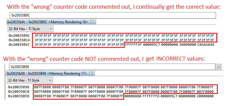
    So, here's the interesting thing: When I add a counter to count the wrong values (code lines 21 and 74-77) an incorrect (yet consistent) value is read from the accelerometer.  However, when I comment out lines 21 and 74-77 the correct value is read from the accelerometer.  This is shown in the attached image (see below) where I view the memory of the 100 element array I save the values in.

    Any idea what might be the issue?

    Accelerometer.c
    #include <stdbool.h>
    #include <stdint.h>
    #include "driverlib/gpio.h"
    #include "driverlib/i2c.h"
    #include "driverlib/pin_map.h"
    #include "driverlib/sysctl.h"
    #include "inc/hw_memmap.h"
    #include "Accelerometer.h"
    
    #define SLAVE_ADDRESS 0x1E // 0011110b
    
    #define WHO_AM_I_REGISTER 0x0F
    #define WHO_AM_I_EXPECTED 0x3F
    
    extern uint32_t g_ui32SysClock;  // Defined in main when initializing CPU clock
    
    void AccelerometerInit()
    {
        unsigned char read_values[100];
        uint32_t i = 0;
        uint32_t wrong = 0;
        while(1)
        {
            // We're using I2C module 2
            SysCtlPeripheralEnable(SYSCTL_PERIPH_I2C2);
    
            // Wait for the I2C2 module to be ready.
            while(!SysCtlPeripheralReady(SYSCTL_PERIPH_I2C2)) { }
    
            // I2C2 uses GPIO L (pins PL0 and PL1)
            SysCtlPeripheralEnable(SYSCTL_PERIPH_GPIOL);
            while(!SysCtlPeripheralReady(SYSCTL_PERIPH_GPIOL)) { }
    
            // Configure the pin muxing for I2C2 functions
            GPIOPinConfigure(GPIO_PL0_I2C2SDA);
            GPIOPinConfigure(GPIO_PL1_I2C2SCL);
    
            // Select the I2C function for these pins.
            GPIOPinTypeI2CSCL(GPIO_PORTL_BASE, GPIO_PIN_1);
            GPIOPinTypeI2C(GPIO_PORTL_BASE, GPIO_PIN_0);
    
            // Enable and initialize the I2C2 master module.
            // "false" sets the data rate to 100 kbps.
            I2CMasterInitExpClk(I2C2_BASE, g_ui32SysClock, false);
    
            // Tell the master module what address it will place on the bus when
            // communicating with the slave.  "false" indicates we'll be sending
            // data, not receiving it.
            I2CMasterSlaveAddrSet(I2C2_BASE, SLAVE_ADDRESS, false);
    
            // Place the data to be sent in the data register.  This is a simple
            // "Who am I?" request to the accelerometer.
            I2CMasterDataPut(I2C2_BASE, WHO_AM_I_REGISTER);
    
            // Initiate send of data from the master.
            I2CMasterControl(I2C2_BASE, I2C_MASTER_CMD_SINGLE_SEND);
    
            // Wait until master module is done transferring.
            while(I2CMasterBusy(I2C2_BASE)) { }
    
            // "true" indicates we'll be receiving data from the given slave
            // address
            2CMasterSlaveAddrSet(I2C2_BASE, SLAVE_ADDRESS, true);
    
            // Tell the master to read data.
            I2CMasterControl(I2C2_BASE, I2C_MASTER_CMD_SINGLE_RECEIVE);
    
            // Wait until the slave is done sending data.
            while(I2CMasterBusy(I2C2_BASE)) { }
    
            // Read the data from the master.
            unsigned char dataRead = I2CMasterDataGet(I2C2_BASE);
    
            if(dataRead != 0x3F)
            {
                ++wrong;
            }
    
            read_values[i % 100] = dataRead;
    
            ++i;
        }
    }
    

  • Hello Terence,

    I don't like that the configuration is put inside of the while(1) loop. That isn't a good practice, especially since the peripheral is never disabled at any point.

    If you pull out all of the configuration portions and only leave the Slave Address Set and below in while loop, do you get any better behavior?

    Also in the attached file, one of the functions seems to be misnamed: "2CMasterSlaveAddrSet(I2C2_BASE, SLAVE_ADDRESS, true);" - that's missing an 'I' in the front of it.
  • Hi Ralph - Thanks for pointing out my errors.  You're correct, it was an oversight of mine to put the initialization and configuration of the I2C in the loop.  My mistake.  Also, I must have lost the "I" from the I2CMasterSlaveAddrSet() function when copy and pasting the code into the previously attached file.

    I have an improved version that still has the same issue with getting improper values when querying "Who Am I?" register of the accelerometer.  This code (the entire program in main.c) is attached - no copy and pasting this time.

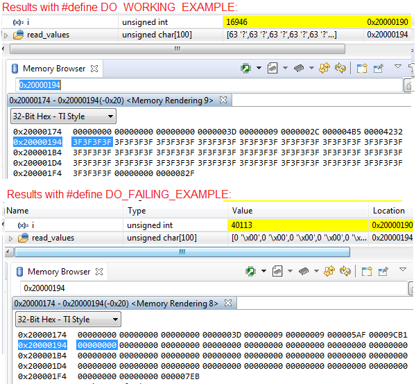
    Also, this time I use #defines (DO_WORKING_EXAMPLE vs DO_FAILING_EXAMPLE).  Looking at the attached code you'll see the working version simply loops through the I2C calls indefinitely to get the value and the failing example does the same, but calling a function which returns the value.

    Below are screenshots of variables and memory values for both cases (working and failing).

    Any ideas you might have of what the issue is would be very much appreciated.

    7382.main.c
    #include <stdbool.h>
    #include <stdint.h>
    #include "driverlib/gpio.h"
    #include "driverlib/i2c.h"
    #include "driverlib/pin_map.h"
    #include "driverlib/rom.h"
    #include "driverlib/rom_map.h"
    #include "driverlib/sysctl.h"
    #include "inc/hw_memmap.h"
    
    #define SLAVE_ADDRESS 0x1E // 0011110b
    
    #define WHO_AM_I_REGISTER 0x0F
    #define WHO_AM_I_EXPECTED 0x3F
    
    #define DO_WORKING_EXAMPLE
    
    uint32_t g_ui32SysClock;
    
    unsigned char ReadReg();
    
    int main(void)
    {
        // Configure the system clock
        MAP_SysCtlMOSCConfigSet(SYSCTL_MOSC_HIGHFREQ); // Set the configuration of the main oscillator (MOSC) control.
                                                       // SYSCTL_MOSC_HIGHFREQ -- Indicates the MOSC is greater than 10MHz
        g_ui32SysClock = MAP_SysCtlClockFreqSet(
            (SYSCTL_XTAL_25MHZ | SYSCTL_OSC_MAIN | SYSCTL_USE_PLL | SYSCTL_CFG_VCO_480), 120000000);
                                                       // Set the system clock frequency to run from the PLL at 120MHz
                                                       // SYSCTL_XTAL_25MHZ  -- Indicates an external crystal frequency of 25 MHz
                                                       // SYSCTL_OSC_MAIN    -- Use external crystal or oscillator
                                                       // SYSCTL_USE_PLL     -- Selects PLL output as system clock
                                                       // SYSCTL_CFG_VCO_480 -- Sets PLL VCO output to 480 MHz
        unsigned char read_values[100];
        uint32_t i = 0;
    
        // We're using I2C module 2
        SysCtlPeripheralEnable(SYSCTL_PERIPH_I2C2);
    
        // Wait for the I2C2 module to be ready.
        while(!SysCtlPeripheralReady(SYSCTL_PERIPH_I2C2)) { }
    
        // I2C2 uses GPIO L (pins PL0 and PL1)
        SysCtlPeripheralEnable(SYSCTL_PERIPH_GPIOL);
        while(!SysCtlPeripheralReady(SYSCTL_PERIPH_GPIOL)) { }
    
        // Configure the pin muxing for I2C2 functions
        GPIOPinConfigure(GPIO_PL0_I2C2SDA);
        GPIOPinConfigure(GPIO_PL1_I2C2SCL);
    
        // Select the I2C function for these pins.
        GPIOPinTypeI2CSCL(GPIO_PORTL_BASE, GPIO_PIN_1);
        GPIOPinTypeI2C(GPIO_PORTL_BASE, GPIO_PIN_0);
    
        // Enable and initialize the I2C2 master module.
        // "false" sets the data rate to 100 kbps.
        I2CMasterInitExpClk(I2C2_BASE, g_ui32SysClock, false);
    
        while(1)
        {
    #ifdef DO_FAILING_EXAMPLE
            read_values[i % 100] = ReadReg();
    #endif
    #ifdef DO_WORKING_EXAMPLE
            // Tell the master module what address it will place on the bus when
            // communicating with the slave.  "false" indicates we'll be sending
            // data, not receiving it.
            I2CMasterSlaveAddrSet(I2C2_BASE, SLAVE_ADDRESS, false);
    
            // Place the data to be sent in the data register.  This is a simple
            // "Who am I?" request to the accelerometer.
            I2CMasterDataPut(I2C2_BASE, WHO_AM_I_REGISTER);
    
            // Initiate send of data from the master.
            I2CMasterControl(I2C2_BASE, I2C_MASTER_CMD_SINGLE_SEND);
    
            // Wait until master module is done transferring.
            while(I2CMasterBusy(I2C2_BASE)) { }
    
            // "true" indicates we'll be receiving data from the given slave
            // address
            I2CMasterSlaveAddrSet(I2C2_BASE, SLAVE_ADDRESS, true);
    
            // Tell the master to read data.
            I2CMasterControl(I2C2_BASE, I2C_MASTER_CMD_SINGLE_RECEIVE);
    
            // Wait until the slave is done sending data.
            while(I2CMasterBusy(I2C2_BASE)) { }
    
            // Read the data from the master.
            read_values[i % 100] = I2CMasterDataGet(I2C2_BASE);
    #endif
            ++i;
        }
    }
    
    unsigned char ReadReg()
    {
            // Tell the master module what address it will place on the bus when
            // communicating with the slave.  "false" indicates we'll be sending
            // data, not receiving it.
            I2CMasterSlaveAddrSet(I2C2_BASE, SLAVE_ADDRESS, false);
    
            // Place the data to be sent in the data register.  This is a simple
            // "Who am I?" request to the accelerometer.
            I2CMasterDataPut(I2C2_BASE, WHO_AM_I_REGISTER);
    
            // Initiate send of data from the master.
            I2CMasterControl(I2C2_BASE, I2C_MASTER_CMD_SINGLE_SEND);
    
            // Wait until master module is done transferring.
            while(I2CMasterBusy(I2C2_BASE)) { }
    
            // "true" indicates we'll be receiving data from the given slave
            // address
            I2CMasterSlaveAddrSet(I2C2_BASE, SLAVE_ADDRESS, true);
    
            // Tell the master to read data.
            I2CMasterControl(I2C2_BASE, I2C_MASTER_CMD_SINGLE_RECEIVE);
    
            // Wait until the slave is done sending data.
            while(I2CMasterBusy(I2C2_BASE)) { }
    
            // Read the data from the master.
            return I2CMasterDataGet(I2C2_BASE);
    }
    

  • Just a bit more info: I've hooked up my logic analyzer to PL0 and PL1.  See below for the resulting screenshot.  Note that I get the same data displayed (as shown below) *BOTH* when using #define DO_WORKING_EXAMPLE *AND* #define DO_FAILING_EXAMPLE.  This makes me think it's some sort of timing issue with reading the data register...  However, what's more concerning to me is that I thought I2C was BIDIRECTIONAL communication - clearly we see that I'm writing 0x0F to slave address  0x1e, HOWEVER, I'm never seeing the 0x3F value the board should be receiving from the accelerometer in response...  Anyone have any ideas???

  • I2CMasterDataGet(I2C2_BASE) returns uint32_t data type. I see you're using unsigned char. Could be that?
  • Hi Helder - Thanks for the response, however, no luck. I changed ReadReg() to return a uint32_t and read_values to be an array of uint32_t's and the problem still persists. :(
  • Hello Terence,

    Regarding I2C, it is not bi-directional. It can handle multiple devices, but all communication is single ended as there is only one data line so it cannot be bi-directional.

    EDIT: Wow so sorry but I had a major mental lapse in my original posting, I was thinking full vs half duplex. Yes I2C is Bi-Directional. So yes you should see the Slave Data on your SDA line.

    You should be seeing the expected result on the I2C lines. For the working example, you get the right result on the TM4C device, but you don't see it on the I2C lines? If so, is your lab tool configured to properly recognize the slave device reply? That's the only thing I can think of on that front.

  • Hello Terence,

    I edited my prior post to fix misinformation from a mental lapse, please read the edit, sorry!

  • Try to change to 4.7K resistors on the I2C lines, if you're using some high values. Also, wouldn't hurt to add delays between your commands, I'm not sure if while(I2CMasterBusy(I2C2_BASE)) respects your device timings...I had a similar problem with my MPU6050.

    I'll check later if I can help with my MPU6050 code.

  • Heder - I'm not sure what you mean by "change to 4.7K on the I2C lines".  Can you elaborate?  I have toyed some with adding various delays (SysCtlDelay calls with various values) and not finding anything that consistently helps.  However, I have some more info: 

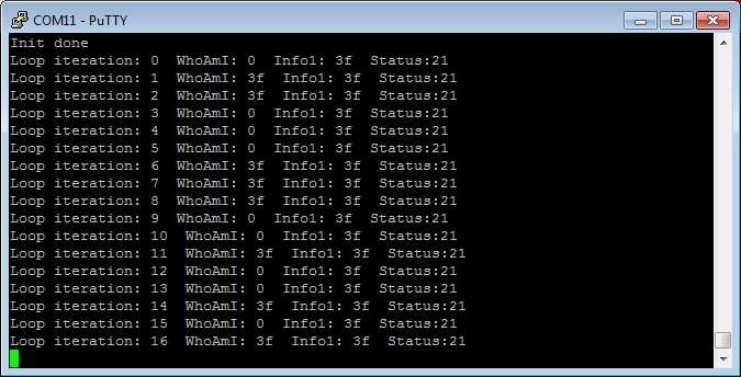
    I've extended my example code (attached) to query multiple registers and report them to a terminal using UART (screenshot below).  As can be seen in the terminal program, the values read by the software differ from iteration to iteration.  I expect to be getting 0x3F for "who am I", 0x21 for "info1" and probably 0x0F for "status".  Based on what's displayed (in the Putty terminal screenshot), it looks like I'm reading the data register at improper times...

    What's interesting is that what I observe using my logic analyzer always appears consistent (screenshot below).  I've captured many instances of the I2C communication and it always is exactly as shown in the screenshot below.  I always see the expected 0x3F and 0x21 values for "who am I" and "info1", and always see 0x00 for "status".  Though I would expect to see 0x0F for status, it is possible 0x00 is a valid value.

    If anyone has any ideas what might be happening, I'd very much appreciate your feedback.  Thank you.

    5672.main.c
    #include <stdbool.h>
    #include <stdint.h>
    #include "driverlib/gpio.h"
    #include "driverlib/i2c.h"
    #include "driverlib/pin_map.h"
    #include "driverlib/rom.h"
    #include "driverlib/rom_map.h"
    #include "driverlib/sysctl.h"
    #include "inc/hw_memmap.h"
    #include "utils/uartstdio.h"
    
    #define SLAVE_ADDRESS 0x1E // 0011110b
    
    #define INFO1_REGISTER 0x0D
    #define WHO_AM_I_REGISTER 0x0F
    #define STATUS_REGISTER  0x27
    #define OUT_X_L_REGISTER 0x28
    #define OUT_X_H_REGISTER 0x29
    #define OUT_Y_L_REGISTER 0x2A
    #define OUT_Y_H_REGISTER 0x2B
    #define OUT_Z_L_REGISTER 0x2C
    #define OUT_Z_H_REGISTER 0x2D
    
    #define WHO_AM_I_EXPECTED 0x3F
    
    #define UART_BAUD_RATE 115200
    #define UART_PORT_NUMBER 0
    
    void ConfigureUART(uint32_t SysClock);
    uint32_t QueryAccelRegister(uint32_t theRegister);
    void WriteAccel(uint8_t registerToWrite);
    uint32_t ReadAccel();
    void IdentifyAccel();
    
    int main(void)
    {
        // Configure the system clock
        MAP_SysCtlMOSCConfigSet(SYSCTL_MOSC_HIGHFREQ); // Set the configuration of the main oscillator (MOSC) control.
                                                       // SYSCTL_MOSC_HIGHFREQ -- Indicates the MOSC is greater than 10MHz
        uint32_t SysClock = MAP_SysCtlClockFreqSet(
            (SYSCTL_XTAL_25MHZ | SYSCTL_OSC_MAIN | SYSCTL_USE_PLL | SYSCTL_CFG_VCO_480), 120000000);
                                                       // Set the system clock frequency to run from the PLL at 120MHz
                                                       // SYSCTL_XTAL_25MHZ  -- Indicates an external crystal frequency of 25 MHz
                                                       // SYSCTL_OSC_MAIN    -- Use external crystal or oscillator
                                                       // SYSCTL_USE_PLL     -- Selects PLL output as system clock
                                                       // SYSCTL_CFG_VCO_480 -- Sets PLL VCO output to 480 MHz
        ConfigureUART(SysClock);
    
        // We're using I2C module 2
        SysCtlPeripheralEnable(SYSCTL_PERIPH_I2C2);
    
        // Wait for the I2C2 module to be ready.
        while(!SysCtlPeripheralReady(SYSCTL_PERIPH_I2C2)) { }
    
        // I2C2 uses GPIO L (pins PL0 and PL1)
        SysCtlPeripheralEnable(SYSCTL_PERIPH_GPIOL);
        while(!SysCtlPeripheralReady(SYSCTL_PERIPH_GPIOL)) { }
    
        // Configure the pin muxing for I2C2 functions
        GPIOPinConfigure(GPIO_PL0_I2C2SDA);
        GPIOPinConfigure(GPIO_PL1_I2C2SCL);
    
        // Select the I2C function for these pins.
        GPIOPinTypeI2CSCL(GPIO_PORTL_BASE, GPIO_PIN_1);
        GPIOPinTypeI2C(GPIO_PORTL_BASE, GPIO_PIN_0);
    
        // Enable and initialize the I2C2 master module.
        // "false" sets the data rate to 100 kbps.
        I2CMasterInitExpClk(I2C2_BASE, SysClock, false);
    
        UARTprintf("Init done\n");
    
        // Maybe need a delay for accelerometer to power up and etc???
        SysCtlDelay(20000000);
    
        uint32_t counter = 0;
    
        while(1)
        {
            uint32_t whoAmI = QueryAccelRegister(WHO_AM_I_REGISTER);
            uint32_t info1 = QueryAccelRegister(INFO1_REGISTER);
            uint32_t status = QueryAccelRegister(STATUS_REGISTER);
            UARTprintf("Loop iteration: %d  WhoAmI: %x  Info1: %x  Status:%x\n", counter, whoAmI, info1, status);
    		SysCtlDelay(20000000);
    		++counter;
        }
    }
    
    uint32_t QueryAccelRegister(uint32_t theRegister)
    {
        SysCtlDelay(4000);
        WriteAccel(theRegister);
        SysCtlDelay(4000);
        return ReadAccel();
    }
    
    void ConfigureUART(uint32_t SysClock)
    {
        // Enable the GPIO Peripheral used by the UART.
        SysCtlPeripheralEnable(SYSCTL_PERIPH_GPIOA);
    
        // Enable UART0
        SysCtlPeripheralEnable(SYSCTL_PERIPH_UART0);
    
        // Configure GPIO Pins for UART mode.
        GPIOPinConfigure(GPIO_PA0_U0RX);
        GPIOPinConfigure(GPIO_PA1_U0TX);
        GPIOPinTypeUART(GPIO_PORTA_BASE, GPIO_PIN_0 | GPIO_PIN_1);
    
        // Initialize the UART for console I/O.
        UARTStdioConfig(UART_PORT_NUMBER, UART_BAUD_RATE, SysClock);
    }
    
    void WriteAccel(uint8_t value)
    {
        // Tell the master module what address it will place on the bus when
        // communicating with the slave.  "false" indicates we'll be sending
        // data, not receiving it.
        I2CMasterSlaveAddrSet(I2C2_BASE, SLAVE_ADDRESS, false);
    
        // Place the data to be sent in the data register.  This is a simple
        // "Who am I?" request to the accelerometer.
        I2CMasterDataPut(I2C2_BASE, value);
    
        // Initiate send of data from the master.
        I2CMasterControl(I2C2_BASE, I2C_MASTER_CMD_SINGLE_SEND);
    
        // Wait until master module is done transferring.
        while(I2CMasterBusy(I2C2_BASE)) { }
    
        // Check for any error
        uint32_t errorCode = I2CMasterErr(I2C2_BASE);
        if(errorCode != I2C_MASTER_ERR_NONE)
        {
            UARTprintf("Error writing to accel: %d\n", errorCode);
        }
    }
    
    uint32_t ReadAccel()
    {
        // "true" indicates we'll be receiving data from the given slave
        // address
        I2CMasterSlaveAddrSet(I2C2_BASE, SLAVE_ADDRESS, true);
    
        // Tell the master to read data.
        I2CMasterControl(I2C2_BASE, I2C_MASTER_CMD_SINGLE_RECEIVE);
    
        // Wait until the slave is done sending data.
        while(I2CMasterBusy(I2C2_BASE)) { }
    
        // Check for any error
        uint32_t errorCode = I2CMasterErr(I2C2_BASE);
        if(errorCode != I2C_MASTER_ERR_NONE)
        {
            UARTprintf("Error reading from accel: %d\n", errorCode);
        }
    
        // Read the data from the master.
        return I2CMasterDataGet(I2C2_BASE);
    }
    

  • Terence D said:

    Heder - I'm not sure what you mean by "change to 4.7K on the I2C lines".  Can you elaborate?  

    I mean the pullup resistors on the SCL and SDA lines may be a bit too high (causing timing issues), assuming you are not working with a pre-assembled module that already includes the proper resistors.

  • Helder Sales said:

    Terence D

    Heder - I'm not sure what you mean by "change to 4.7K on the I2C lines".  Can you elaborate?  

    I mean the pullup resistors on the SCL and SDA lines may be a bit too high (causing timing issues), assuming you are not working with a pre-assembled module that already includes the proper resistors.

    I'm sorry, I'm still not following.  Are you suggesting physically adding a 4.7K resistor in between the connection from the Tiva board and the accelerometer, or is this a setting I can access thru the TivaWare Peripheral Library when configuring the PL0/PL1 I2C communication?

  • Hello Terence,

    He is referring to the Pull-up Resistors that are crucial for successful I2C communication. Check the schematics for the I2C module to see if they have any pull-ups and what value they are. That said if you are always getting the bytes successfully over the LSA, there shouldn't be an issue with the communication of the I2C lines.

    I haven't had a chance to review your code again but will try and do so soon and provide feedback on what may be occurring. Ideally I'll try and use a different I2C slave device I have on my desk to try and read a register and see if I can replicate the behavior.
  • It appears that you've 'mangled' the 'Slave I2C's Register Addresses (at least the third one).'      I've placed your (suspected) issue in highlight.

    Note that you've addressed Register 0x27 - was not Register 0x0E - better targeted?      Should not the 'CORRECT REGISTER SEQUENCE'  have been:  '0x0F, 0x0D, 0x0E?'      Support for this claim follows:

    May my firm & I respectfully 'disagree' w/Vendor Agent's suggestion ...  to use another device?     Firm/I have (long found) such devices to be at/near 'best in class' - when the 'detailed data manual' is (really) followed.    

    Note too - that data sheet's advice:

    'The LIS3DSH features a Data-Ready signal (DRDY) which indicates when a new set of measured acceleration data is available, therefore simplifying data synchronization in the digital system that uses the device.    It is unknown if you've employed such 'DRDY' signal - which enables MAXIMUM Transfer Speed - should that be desired...'

    The suggestion of, 'lowered value pull-ups' - FAILS in my book - as 'SO MUCH DATA' arrives CORRECTLY!      And of course - there exists a 'grievous' Register Addressing Error.    (ALL of the facts must be absorbed - then weighed!)

    The device IS available on a, 'pro-designed & implemented' Eval Board.    Less than experienced users are (highly) unlikely to succeed w/such fine-pitch device - when 'hand assembling!'

    And - is it 'NOT' to be noted - that at least <this portion> of your issue runs <contrary> to your post's Subject: "I2C Instructions - from Datasheet!"  (LIKE'd the irony...)

  • Hello cb1,

    I didn't suggest Terence use another device, but rather since I don't have his module I would try and replicate the issue with on my end with my own I2C slave as it sounded from my reading (unless I missed something) that part of the issue is not I2C comms but how the data goes from peripheral register -> UART display in the case where the WhoAmI command prints out 0x00.
  • Hello Ralph,

    As you know - I've moved on - there ARE 'more appreciative" (i.e. somewhat appreciative) hunting grounds.     My rapid scan of your writing locked onto, 'Another Device.'

    May I note that his 'Who Am I' command was correct - it was an INCORRECT 3rd Register Address (as I just detailed) which was flawed - and which may have, 'Served to Disorder the system.'    

    There is also a powerful 'DRDY' signal - which proves of much value...    

    Poster's issue is almost certainly the result of ... ... 'Violation of KISS' - great 'Attention to Detail' (was) and is required - and his logic analyzer presentation presented a CLEAR MISTAKE!     AND ... when devices are as 'complex' and high-performing - as this one - there are (likely) to appear certain 'special' care/handling guidelines - unlikely to 'overlap' - in any (different) device.    As an example - the data sheet for poster's device advises of a (somewhat) strict - 'Start-Stop' and/or 'Inter-Byte Transfer' Timing Specification - which is unlikely to be equaled by (other) I2C devices...

    I would state - with great confidence - that your TM4C is 'Completely Off-the-Hook' in ANY responsibility for poster's 'irregular data collection.'      High stack of chips resides upon this being a, 'System Issue' - brought about by,  "incomplete attention to - or compliance with - needed System DETAIL!"      As I've noted so often (along w/the equally departed Robert) NOT ALWAYS does the, "Sun & Moon" arise ONLY ... w/the MCU...

    Such would ONLY be detected via 'KISS' - and a full/proper read/absorption - of poster's device data manual...

  • So, good news: It appears I have it properly working, tho it's not ultra elegant.  Long story short, on the write I'm using BURST commands (even tho I just need to write one byte).  And on the reads I do a I2C_MASTER_CMD_BURST_SEND_START (even though I'm just reading one byte) and then a I2C_MASTER_CMD_SINGLE_RECEIVE.  I have some additional time delays when reading/writing in a row as without them my logic analyzer was showing bus errors.

    cb1_mobile said:

    It appears that you've 'mangled' the 'Slave I2C's Register Addresses (at least the third one).'      Note that you've addressed Register 0x27 - was not Register 0x0E - better targeted?      Should not the 'CORRECT REGISTER SEQUENCE'  have been:  '0x0F, 0x0D, 0x0E?'      

    CB1 - Great to get a response from you!  I say this with 100% sincerity: Of all the forums I participate in, you are among my favorite fellow participant.  However, I regret to inform you that I believe you're mistaken about the third register being wrong.  As mentioned in my previous post I was interested in reading the status register, which indeed is 0x27.  0x0E was not of much interest to me since it simply contained a value of zero.

    cb1_mobile said:

    Note too - that data sheet's advice:

    'The LIS3DSH features a Data-Ready signal (DRDY) which indicates when a new set of measured acceleration data is available, therefore simplifying data synchronization in the digital system that uses the device.    It is unknown if you've employed such 'DRDY' signal - which enables MAXIMUM Transfer Speed - should that be desired...'

    Thank you.  This is a great suggestion and something I will be looking into as soon as I finish this post.  I did however want to get the accelerometer working in its most basic way before moving forward...  Which thankfully, I have now achieved..

    cb1_mobile said:

    And - is it 'NOT' to be noted - that at least <this portion> of your issue runs <contrary> to your post's Subject: "I2C Instructions - from Datasheet!"  (LIKE'd the irony...)

    Yes.  No argument from me here.  This thread has made a bit of a journey.  If you look back to the beginning you'll see I attempted to follow straight datasheet I2C instructions for better visibility into the issue (as opposed to using the TivaWare Std Peripheral Lib).  I'll see if I can change the thread title, thinking I can't, but I'll try.

    Cheers gents!  Thanks for the assistance!

  • Hi Terence,

    Great to hear of your progress! If you edit your original post, it may let you change the title. If not, I can do it for you (if so though would be helpful to have a title provided so I don't have to come up with it on my end haha).
  • Thank you, Terence ...  yours are very nice ...  much appreciated, kind words.      Appears that the 'Mangler du Jour' was (this guy.)      And NOT ... for the first time...

    I do believe your sensor choice to be superb - these rather special device features - along w/the 'DRDY' signal justify:

    • The self-test capability allows the user to check the functioning of the sensor in the final application.
    • The device can be configured to generate interrupt signals activated by user-defined motion patterns.
    • The LIS3DSH has an integrated first-in, first-out (FIFO) buffer allowing the user to store data in order to limit intervention by the host processor.

    I believe that (even) further 'read/review' of the following device's section (5.1.1) will promote your solution - to (near) elegant!    (if not to full-blown, elegant!) 

    5.1.1   I2C Operation:

    "The slave address is completed with a read/write bit. If the bit is ‘1’ (Read), a repeated start (SR) condition must be issued after the two sub-address bytes; if the bit is ‘0’ (Write), the master transmits to the slave with direction unchanged."    Page 23/24 of the device's manual (very) nicely diagram & detail...   (always helps me)

    Again - thanks much for your kind words & firm/I wish you great success...

  • cb1_mobile said:

    I believe that (even) further 'read/review' of the following device's section (5.1.1) will promote your solution - to (near) elegant!    (if not to full-blown, elegant!) 

    5.1.1   I2C Operation:

    "The slave address is completed with a read/write bit. If the bit is ‘1’ (Read), a repeated start (SR) condition must be issued after the two sub-address bytes; if the bit is ‘0’ (Write), the master transmits to the slave with direction unchanged."    Page 23/24 of the device's manual (very) nicely diagram & detail...   (always helps me)

    You are correct, sir.  I'm now performing a "burst read" from the accelerometer registers to receive all six bytes of data (3 axes, hi/lo bytes for each).  Using I2C "fast mode" this takes about 375 microseconds as compared to upwards of 1.5+ milliseconds to receive all six bytes of data reading one register at a time.

    cb1_mobile said:

    I do believe your sensor choice to be superb - these rather special device features - along w/the 'DRDY' signal

    For my use case I'm not seeing value in the DRDY option - possibly I'm over looking something?  I'll explain my use case: I want to periodically - every 50 milliseconds - check the position of the accelerometer and perform some calculations using the most recent accelerometer x, y, z values.  So, I have a timer interrupt occurring every 50 milliseconds.  At the beginning of the interrupt I read the accelerometer positions then perform said calculations.

    I've set the output data rate to 100 Hz by setting the high 4 bits of CTRL_REG4 to 0110b.  Worst case scenario, my accelerometer values are 10 milliseconds old, which is within my requirements.

    I don't see how DRDY will help me here as it will not allow me any more up-to-date accelerometer readings than my current method, and furthermore, it will cause interrupts to occur every 10 milliseconds, each using ~375 microseconds to read values I only use 20% of the time.

    Note that there is other processing occurring aside to the aforementioned accelerometer calculations which I'd prefer not to interrupt with accelerometer reads that are usually (80% of the time) of no value.

    Am I missing something?

  • Terence D said:
    For my use case I'm not seeing value in the DRDY option - possibly I'm over looking something?

    I'll attempt to, 'Make the case for the use of 'DRDY:'

    • That capability (and extra pin) is 'unusual' for such an 'I2C' device - cost the vendor to add/include.
    • Vendor is (surely) more 'connected & cunning' than you/I - multiple other users.     Is it not (reasonable) to assume that the vendor, 'Knew something!'
    • Your 100Hz output rate 'chokes down' the potential data rate by a factor of 'SIXTEEN!'
    • I don't agree w/your ID of 'Worst case' - would that not instead be, 'the likely potential to MISS key/critical data' - potentially captured - during that (enormous) 10mS of 'dead-time?' 
    • By enabling your MCU - and NOT your Sensor - to 'Dictate the terms of, when to acquire' - you invite the possibility of reading (suspect) values!      'Achieved during the Update Process!'  see * (below)
    • As a general rule (subject to all the weaknesses of such generality) - the 'Acquisition of MORE DATA ... at shorter intervals - trumps LESS DATA/Longer Intervals!'

    While neither my firm nor I have used this particular device - there are 'multiple use cases' for the capture of such 'tri-axis, acceleration data' - at far higher than 100Hz rates!     Vibration detection, Machine imbalance, motor bearing wear - all immediately arrive.    

    Yet more - if you read/review the product specs for those w/in this field - producing commercially 'successful' product - it is (extremely) doubted that (ANY) will tout their 100HZ update rate!

    There exist ARM MCUs which run at 50% increased System Clocks (and higher) which better accommodate the 'increased demands' which such 'Advanced Sensors' place upon the MCU.    Is it wise to mate such a, 'Performance based Sensor' - with an MCU which,  'forces such compromise?'

    *  from the sensor manual (pg 39, Cntl 4 Reg): When the BDU is activated (BDU = ‘1’), the content of the output registers is not updated until both MSb and LSb are read which avoids reading values related to different sample times.     Use of DRDY  prevents such misfortune...     Perhaps more colorfully - allowing the MCU to, 'Call the sensor read shots' (when/while BLIND to the 'Readiness of Data') - proves 'not far' from one 'Blind guy asking another' (so inflicted) ...  "Hey Buddy - is it SAFE to cross?"

    While what you have developed (appears) sufficient for now - my preference is to see your hard work & effort rewarded with a higher performance implementation - which may be 'RE-USED' - long into the future.    That 'Design Strategically ONCE' - then  'repeatedly DEPLOY' ... is How ... you co-found - then take Tech Firm  PUBLIC!

    Do note - I've exited this forum - should you wish to continue - kindly, 'Enable Conversations' (via the forum's registration page) so that we may exchange via 'PM.'

    Again your kind words were appreciated - even your 'doubt' - which has been (somewhat (maybe)) alleviated herein...     (Short-term and/or compromised 'solutions' - prove 'unlikely' to inspire...)