This thread has been locked.

If you have a related question, please click the "Ask a related question" button in the top right corner. The newly created question will be automatically linked to this question.

EK-TM4C1294XL: TIVA CAN Bus not working for EK-TM4C1294XL Rev.D board

Part Number: EK-TM4C1294XL
Other Parts Discussed in Thread: SN65HVD233-HT, SN74LVC4245A, SN74LV244A

I am working on CAN bus.

I am using simple_tx and simple_rx code given in example folder (peripheral-CAN).

I have modified that code since I don't want to use UART and made code simple.

I have followed this thread: 

But this doesn't work for me.

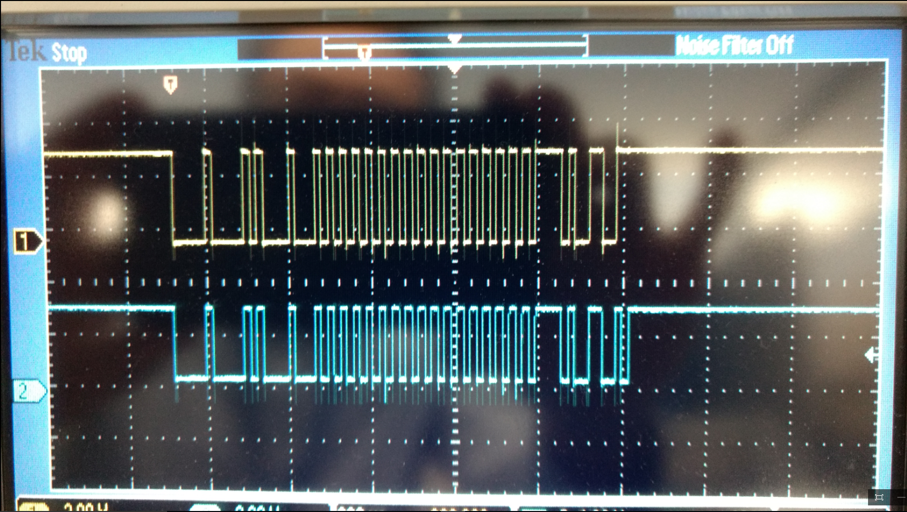
Different hardware connections and corresponding output waveform, I have attached in following document. Please see that.

Problem TI Post.pdf

and the hardware connection :

All jumpers are in default position.


////////////////////////////////  SIMPLE_TX CODE 
#include <stdbool.h>
#include <stdint.h>
#include "inc/hw_can.h"
#include "inc/hw_ints.h"
#include "inc/hw_memmap.h"
#include "driverlib/can.h"
#include "driverlib/gpio.h"
#include "driverlib/interrupt.h"
#include "driverlib/pin_map.h"
#include "driverlib/sysctl.h"
#include "driverlib/uart.h"
#include "utils/uartstdio.h"

volatile uint32_t g_ui32MsgCount = 0;
unsigned int sysClock;
volatile bool g_bErrFlag = 0;

void InitConsole(void)
{
    SysCtlPeripheralEnable(SYSCTL_PERIPH_GPIOD); // enable UART0 GPIO peripheral
    GPIOPinConfigure(GPIO_PD4_U2RX);
    GPIOPinConfigure(GPIO_PD5_U2TX);
    SysCtlPeripheralEnable(SYSCTL_PERIPH_UART2);
    UARTClockSourceSet(UART2_BASE, UART_CLOCK_PIOSC);
    GPIOPinTypeUART(GPIO_PORTD_BASE, GPIO_PIN_4 | GPIO_PIN_5);
    //UARTStdioConfig(0, 115200, sysClock);
}

void SimpleDelay(void)
{
    SysCtlDelay(40000000);
}

void CANIntHandler(void)
{
    uint32_t ui32Status;

    ui32Status = CANIntStatus(CAN1_BASE, CAN_INT_STS_CAUSE);

    if(ui32Status == CAN_INT_INTID_STATUS)
    {

        ui32Status = CANStatusGet(CAN1_BASE, CAN_STS_CONTROL);

        g_bErrFlag = 1;
    }

    else if(ui32Status == 1)
    {

        CANIntClear(CAN1_BASE, 1);

        g_ui32MsgCount++;

        g_bErrFlag = 0;
    }

    else
    {

    }
}

int main(void)
  {
    tCANMsgObject sCANMessage;
    uint32_t ui32MsgData=0;
    uint8_t *pui8MsgData;

    pui8MsgData = (uint8_t *)&ui32MsgData;

    sysClock = SysCtlClockFreqSet((SYSCTL_XTAL_25MHZ | SYSCTL_OSC_MAIN | SYSCTL_USE_PLL | SYSCTL_CFG_VCO_480), 120000000);SimpleDelay();

    //InitConsole();
    SysCtlPeripheralEnable(SYSCTL_PERIPH_GPION);
    GPIOPinTypeGPIOOutput(GPIO_PORTN_BASE, GPIO_PIN_0|GPIO_PIN_1);
    SysCtlPeripheralEnable(SYSCTL_PERIPH_GPIOB);SimpleDelay();
    GPIOPinConfigure(GPIO_PB0_CAN1RX);
    GPIOPinConfigure(GPIO_PB1_CAN1TX);
    GPIOPinTypeCAN(GPIO_PORTB_BASE, GPIO_PIN_0 | GPIO_PIN_1);
    SysCtlPeripheralEnable(SYSCTL_PERIPH_CAN1);
    CANInit(CAN1_BASE);SimpleDelay();
    CANBitRateSet(CAN1_BASE, SysCtlClockGet(), 500000);SimpleDelay();
    CANIntRegister(CAN1_BASE, CANIntHandler); SimpleDelay();
    CANIntEnable(CAN1_BASE, CAN_INT_MASTER | CAN_INT_ERROR | CAN_INT_STATUS);SimpleDelay();
    IntEnable(INT_CAN1);SimpleDelay();
    CANEnable(CAN1_BASE);SimpleDelay();

    ui32MsgData = 0xAA;
    sCANMessage.ui32MsgID = 1;
    sCANMessage.ui32MsgIDMask = 0;
    sCANMessage.ui32Flags = MSG_OBJ_TX_INT_ENABLE;
    sCANMessage.ui32MsgLen = sizeof(pui8MsgData);
    sCANMessage.pui8MsgData = pui8MsgData;

    while(1)
    {
        //UARTprintf("Sending msg: 0x%02X %02X %02X %02X",pui8MsgData[0], pui8MsgData[1], pui8MsgData[2],pui8MsgData[3]);
        GPIOPinWrite(GPIO_PORTN_BASE, GPIO_PIN_0|GPIO_PIN_1, 0x02);
        CANMessageSet(CAN1_BASE, 1, &sCANMessage, MSG_OBJ_TYPE_TX);SimpleDelay();
        GPIOPinWrite(GPIO_PORTN_BASE, GPIO_PIN_0|GPIO_PIN_1, 0x08);SimpleDelay();
        if(g_bErrFlag)
        {
            //UARTprintf(" error - cable connected?\n");
        }
        else
        {
            //UARTprintf(" total count = %u\n", g_ui32MsgCount);
        }
        /*ui32MsgData++;
        if(ui32MsgData>=0x65)
        {
            ui32MsgData = 0x55;
        }*/
        while(1)
        {
        }
    }
    return(0);
}

/////////////////////////////////////////////////  SIMPLE_TX CODE END


/////////////////////////////////////////////////  SIMPLE_RX CODE 

#include <stdbool.h>
#include <stdint.h>
#include "inc/hw_can.h"
#include "inc/hw_ints.h"
#include "inc/hw_memmap.h"
#include "inc/hw_types.h"
#include "driverlib/can.h"
#include "driverlib/gpio.h"
#include "driverlib/interrupt.h"
#include "driverlib/pin_map.h"
#include "driverlib/sysctl.h"
#include "driverlib/uart.h"
#include "utils/uartstdio.h"

unsigned int sysClock;
volatile uint32_t g_ui32MsgCount = 0;
volatile bool g_bRXFlag = 0;

volatile bool g_bErrFlag = 0;


void SimpleDelay(void)
{
    SysCtlDelay(20000000);
}
//*****************************************************************************
void InitConsole(void)
{
    SysCtlPeripheralEnable(SYSCTL_PERIPH_GPIOD); // enable UART0 GPIO peripheral
    GPIOPinConfigure(GPIO_PD4_U2RX);
    GPIOPinConfigure(GPIO_PD5_U2TX);
    SysCtlPeripheralEnable(SYSCTL_PERIPH_UART2);
    UARTClockSourceSet(UART2_BASE, UART_CLOCK_PIOSC);
    GPIOPinTypeUART(GPIO_PORTD_BASE, GPIO_PIN_4 | GPIO_PIN_5);
    //UARTStdioConfig(0, 115200, sysClock);
}

void
CANIntHandler(void)
{
    uint32_t ui32Status;
    ui32Status = CANIntStatus(CAN1_BASE, CAN_INT_STS_CAUSE);
    if(ui32Status == CAN_INT_INTID_STATUS)
    {
        ui32Status = CANStatusGet(CAN1_BASE, CAN_STS_CONTROL);
        g_bErrFlag = 1;
    }

    else if(ui32Status == 1)
    {
        CANIntClear(CAN1_BASE, 1);
        g_ui32MsgCount++;
        g_bRXFlag = 1;
        g_bErrFlag = 0;
    }

    else
    {
    }
}

int main(void)
{


    tCANMsgObject sCANMessage;
    uint8_t pui8MsgData[8];

    sysClock = SysCtlClockFreqSet((SYSCTL_XTAL_25MHZ | SYSCTL_OSC_MAIN | SYSCTL_USE_PLL | SYSCTL_CFG_VCO_480), 120000000);
    //InitConsole();
    SysCtlPeripheralEnable(SYSCTL_PERIPH_GPION);
    GPIOPinTypeGPIOOutput(GPIO_PORTN_BASE, GPIO_PIN_0|GPIO_PIN_1);

    SysCtlPeripheralEnable(SYSCTL_PERIPH_GPIOB);
    GPIOPinConfigure(GPIO_PB0_CAN1RX);
    GPIOPinConfigure(GPIO_PB1_CAN1TX);
    GPIOPinTypeCAN(GPIO_PORTB_BASE, GPIO_PIN_0 | GPIO_PIN_1);
    SysCtlPeripheralEnable(SYSCTL_PERIPH_CAN1);SimpleDelay();
    CANInit(CAN1_BASE);SimpleDelay();
    CANBitRateSet(CAN1_BASE, SysCtlClockGet(), 500000);SimpleDelay();
    CANIntRegister(CAN1_BASE, CANIntHandler); SimpleDelay();
    CANIntEnable(CAN1_BASE, CAN_INT_MASTER | CAN_INT_ERROR | CAN_INT_STATUS);SimpleDelay();
    IntEnable(INT_CAN1);SimpleDelay();
    CANEnable(CAN1_BASE);SimpleDelay();
    sCANMessage.ui32MsgIDMask = 0;
    sCANMessage.ui32Flags = MSG_OBJ_RX_INT_ENABLE | MSG_OBJ_USE_ID_FILTER;
    sCANMessage.ui32MsgLen = 8;
    CANMessageSet(CAN1_BASE, 1, &sCANMessage, MSG_OBJ_TYPE_RX);

    for(;;)
    {
        unsigned int uIdx;
        if(g_bRXFlag)
        {
            GPIOPinWrite(GPIO_PORTN_BASE, GPIO_PIN_0|GPIO_PIN_1, 0x08);
            SimpleDelay();
            GPIOPinWrite(GPIO_PORTN_BASE, GPIO_PIN_0|GPIO_PIN_1, 0x02);
            sCANMessage.pui8MsgData = pui8MsgData;
            CANMessageGet(CAN1_BASE, 1, &sCANMessage, 0);
            g_bRXFlag = 0;
            if(sCANMessage.ui32Flags & MSG_OBJ_DATA_LOST)
            {
                //UARTprintf("CAN message loss detected\n");
            }

            //UARTprintf("Msg ID=0x%08X len=%u data=0x",sCANMessage.ui32MsgID, sCANMessage.ui32MsgLen);
            for(uIdx = 0; uIdx < sCANMessage.ui32MsgLen; uIdx++)
            {
                //UARTprintf("%02X ", pui8MsgData[uIdx]);
                if(pui8MsgData[uIdx]==0xAA)
                {
                    GPIOPinWrite(GPIO_PORTN_BASE, GPIO_PIN_0|GPIO_PIN_1, 0x02);SimpleDelay();
                    GPIOPinWrite(GPIO_PORTN_BASE, GPIO_PIN_0|GPIO_PIN_1, 0x08);SimpleDelay();
                    GPIOPinWrite(GPIO_PORTN_BASE, GPIO_PIN_0|GPIO_PIN_1, 0x02);SimpleDelay();
                    GPIOPinWrite(GPIO_PORTN_BASE, GPIO_PIN_0|GPIO_PIN_1, 0x08);SimpleDelay();
                    GPIOPinWrite(GPIO_PORTN_BASE, GPIO_PIN_0|GPIO_PIN_1, 0x02);SimpleDelay();
                    GPIOPinWrite(GPIO_PORTN_BASE, GPIO_PIN_0|GPIO_PIN_1, 0x08);SimpleDelay();
                    GPIOPinWrite(GPIO_PORTN_BASE, GPIO_PIN_0|GPIO_PIN_1, 0x02);SimpleDelay();
                    GPIOPinWrite(GPIO_PORTN_BASE, GPIO_PIN_0|GPIO_PIN_1, 0x08);SimpleDelay();
                }
            }
            //UARTprintf("total count=%u\n", g_ui32MsgCount);
        }
    }

    return(0);
}

/////////////////////////////////////////////////  SIMPLE_RX CODE END


I think I have done some mistake in hardware or in code. I am not able to debug that.

Amit suggested SN65HVD233-HT 3.3-V CAN Transceiver.  

Is it issue of MCP2551 CAN Transceiver because of voltage levels(TTL)..???

I have tried LVTTL to TTL convertor and  TTL to LVTTL convertor , SN74LV244A and SN74LVC4245A. Still getting same error.

Regards,

Krishnat

  • The preferred method of connecting TM4C129 controllers to a CAN bus is through the use of 3.3V CAN transceivers. Here is some more documentation on the CAN bus:

    http://www.ti.com/lit/an/sloa101b/sloa101b.pdf

    The method of connecting two devices on a psuedo CAN bus using diodes like you did in circuit image 4 should work. If you go back to that configuration and capture a scope image of the full CAN frame at both pins PB1 (CAN1TX) and PB0 (CAN1RX) of the device programmed with the simple TX code example, we should see a difference between the two signals when the receiving device asserts the acknowledge signal.

    I see one big problem in the software you modified. In both the TX and RX routines you used the function SysCtlClockGet() in the call to CANBitRateSet(). That function is for TM4C123 devices only and does not work for TM4C129 devices. Instead the call should use the variable ui32SysClock that was initialized in the call to SysCtlClockFreqSet().

        CANBitRateSet(CAN1_BASE, ui32SysClock, 500000);
    

  • HI bob,

    I corrected the code, variable ui32SysClock solved issue.

    I got the same output as Charles Tsai posted in thread i mentioned:

    I have one issue left.

    I am getting CAN frames again and again.

    As you can see that I have configured MSG once in TX code.

    So once ACK is received CAN line should be idle.

    But it goes on transmitting same MSG again. It becomes Idle when I modified the code as

    while(1)
        {
            //UARTprintf("Sending msg: 0x%02X %02X %02X %02X",pui8MsgData[0], pui8MsgData[1], pui8MsgData[2],pui8MsgData[3]);
            GPIOPinWrite(GPIO_PORTN_BASE, GPIO_PIN_0|GPIO_PIN_1, 0x02);
            CANMessageSet(CAN1_BASE, 1, &sCANMessage, MSG_OBJ_TYPE_TX);SimpleDelay();
            GPIOPinWrite(GPIO_PORTN_BASE, GPIO_PIN_0|GPIO_PIN_1, 0x08);SimpleDelay();
            if(g_bErrFlag)
            {
                //UARTprintf(" error - cable connected?\n");
            }
            else
            {
                //UARTprintf(" total count = %u\n", g_ui32MsgCount);
            }
            /*ui32MsgData++;
            if(ui32MsgData>=0x65)
            {
                ui32MsgData = 0x55;
            }*/
           CANMessageClear(CAN1_BASE,1); /////////////////////////*************
            while(1)
            {
            }
        }

     Between two functions CANMessageSet() and CANMessageClear(), I get multiple transmission.

    So I again modified the code as:

    #include <stdbool.h>
    #include <stdint.h>
    #include "inc/hw_can.h"
    #include "inc/hw_ints.h"
    #include "inc/hw_memmap.h"
    #include "driverlib/can.h"
    #include "driverlib/gpio.h"
    #include "driverlib/interrupt.h"
    #include "driverlib/pin_map.h"
    #include "driverlib/sysctl.h"
    #include "driverlib/uart.h"
    #include "utils/uartstdio.h"
    
    volatile uint32_t g_ui32MsgCount = 0;
    uint32_t ui32SysClock=0;
    volatile bool g_bErrFlag = 0;
    volatile bool g_bTXFlag = 0;
    
    void InitConsole(void)
    {
        SysCtlPeripheralEnable(SYSCTL_PERIPH_GPIOD); // enable UART0 GPIO peripheral
        GPIOPinConfigure(GPIO_PD4_U2RX);
        GPIOPinConfigure(GPIO_PD5_U2TX);
        SysCtlPeripheralEnable(SYSCTL_PERIPH_UART2);
        UARTClockSourceSet(UART2_BASE, UART_CLOCK_PIOSC);
        GPIOPinTypeUART(GPIO_PORTD_BASE, GPIO_PIN_4 | GPIO_PIN_5);
        //UARTStdioConfig(0, 115200, sysClock);
    }
    
    void SimpleDelay(void)
    {
        SysCtlDelay(40000000);
    }
    
    void CANIntHandler(void)
    {
        uint32_t ui32Status;
    
        ui32Status = CANIntStatus(CAN1_BASE, CAN_INT_STS_CAUSE);
    
        if(ui32Status == CAN_INT_INTID_STATUS)
        {
    
            ui32Status = CANStatusGet(CAN1_BASE, CAN_STS_CONTROL);
    
            g_bErrFlag = 1;
        }
    
        else if(ui32Status == 1)
        {
    
            CANIntClear(CAN1_BASE, 1);
            g_ui32MsgCount++;
            g_bErrFlag = 0;
            g_bTXFlag = 1;
        }
    
        else
        {
    
        }
    }
    
    int main(void)
      {
        tCANMsgObject sCANMessage;
        uint32_t ui32MsgData=0;
        uint8_t *pui8MsgData;
    
        pui8MsgData = (uint8_t *)&ui32MsgData;
    
        ui32SysClock = SysCtlClockFreqSet((SYSCTL_XTAL_25MHZ | SYSCTL_OSC_MAIN | SYSCTL_USE_PLL | SYSCTL_CFG_VCO_480), 120000000);SimpleDelay();
        //InitConsole();
        SysCtlPeripheralEnable(SYSCTL_PERIPH_GPION);
        GPIOPinTypeGPIOOutput(GPIO_PORTN_BASE, GPIO_PIN_0|GPIO_PIN_1);
        SysCtlPeripheralEnable(SYSCTL_PERIPH_GPIOB);SimpleDelay();
        GPIOPinConfigure(GPIO_PB0_CAN1RX);
        GPIOPinConfigure(GPIO_PB1_CAN1TX);
        GPIOPinTypeCAN(GPIO_PORTB_BASE, GPIO_PIN_0 | GPIO_PIN_1);
        SysCtlPeripheralEnable(SYSCTL_PERIPH_CAN1);
        CANInit(CAN1_BASE);SimpleDelay();
        CANBitRateSet(CAN1_BASE, ui32SysClock, 500000);SimpleDelay();
        CANIntRegister(CAN1_BASE, CANIntHandler); SimpleDelay();
        CANIntEnable(CAN1_BASE, CAN_INT_MASTER | CAN_INT_ERROR | CAN_INT_STATUS);SimpleDelay();
        IntEnable(INT_CAN1);SimpleDelay();
        CANEnable(CAN1_BASE);SimpleDelay();
    
        ui32MsgData = 0xAA;
        sCANMessage.ui32MsgID = 1;
        sCANMessage.ui32MsgIDMask = 0;
        sCANMessage.ui32Flags = MSG_OBJ_TX_INT_ENABLE;
        sCANMessage.ui32MsgLen = sizeof(pui8MsgData);
        sCANMessage.pui8MsgData = pui8MsgData;
    
        while(1)
        {
            //UARTprintf("Sending msg: 0x%02X %02X %02X %02X",pui8MsgData[0], pui8MsgData[1], pui8MsgData[2],pui8MsgData[3]);
            GPIOPinWrite(GPIO_PORTN_BASE, GPIO_PIN_0|GPIO_PIN_1, 0x02);
            CANMessageSet(CAN1_BASE, 1, &sCANMessage, MSG_OBJ_TYPE_TX);SimpleDelay();
            GPIOPinWrite(GPIO_PORTN_BASE, GPIO_PIN_0|GPIO_PIN_1, 0x08);SimpleDelay();
            if(g_bErrFlag)
            {
                //UARTprintf(" error - cable connected?\n");
            }
            else if(g_bTXFlag)
            {
                CANMessageClear(CAN1_BASE,1);
                g_bTXFlag=0;
                //UARTprintf(" total count = %u\n", g_ui32MsgCount);
            }
            /*ui32MsgData++;
            if(ui32MsgData>=0x65)
            {
                ui32MsgData = 0x55;
            }*/
    
            SimpleDelay();
            SimpleDelay();
        }
        return(0);
    }
    

    Still multiple transmission are there but numbers of multiple transmission is reduced.

    Is there any mistake in Code??

    Regards,

    Krishnat

  • Your call to CANMessageSet() is within a while(1) loop. That will cause continuous messages to be sent.
  • while(1)
    {
    //UARTprintf("Sending msg: 0x%02X %02X %02X %02X",pui8MsgData[0], pui8MsgData[1], pui8MsgData[2],pui8MsgData[3]);
    GPIOPinWrite(GPIO_PORTN_BASE, GPIO_PIN_0|GPIO_PIN_1, 0x02);
    CANMessageSet(CAN1_BASE, 1, &sCANMessage, MSG_OBJ_TYPE_TX);SimpleDelay();
    GPIOPinWrite(GPIO_PORTN_BASE, GPIO_PIN_0|GPIO_PIN_1, 0x08);SimpleDelay();
    if(g_bErrFlag)
    {
    //UARTprintf(" error - cable connected?\n");
    }
    else
    {
    //UARTprintf(" total count = %u\n", g_ui32MsgCount);
    }
    /*ui32MsgData++;
    if(ui32MsgData>=0x65)
    {
    ui32MsgData = 0x55;
    }*/
    CANMessageClear(CAN1_BASE,1); /////////////////////////*************
    while(1)
    {
    }
    }

    there are two while loops, because of inner loop msg should be send once.
    but time between CANMessageSet and CANMessageClear there are multiple transmission.
    And second code where I used g_bTXFlag to check transmission is completed or not, has bug. I will modify and post results. Sorry for that.

    Regards,
    Krishnat
  • Code is working Fine.
    Thank you bob.
  • Hey Bob,

    I have encountered new problem in CAN module.
    Please see my new post: e2e.ti.com/.../696119

    Regards,
    Krishnat