This thread has been locked.

If you have a related question, please click the "Ask a related question" button in the top right corner. The newly created question will be automatically linked to this question.

TM4C1294KCPDT: Ethernet Link Issue

Part Number: TM4C1294KCPDT

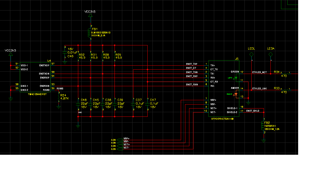
I am bringing up a new design and have followed all the design guides.  I am having issues with certain boards linking properly to some types of Ethernet Switches.  Are there any known issues with this or any recommendations.  I am using and embedded ethernet module with magnetics from xfmrs.com/.../      XFPOEP5-CTGA1-4M.

  • HI,
    I don't really spot anything obvious in your design except that the XFPOEP5-CTGA1-4M is not listed in our datasheet/app note as the recommended transformers. With that said, I think the XFPOEP5-CTGA1-4M should work if it is designed to comply with the IEEE 802.3 standard.

    When you said some boards are having problems, can you be specific? It seems to me that you have different board designs with XFPOEP5-CTGA1-4M that do work. Is this correct? Also you said the problem is only occurring with some types of Ethernet switches. This again creates another variable. Looks like you may have board A and B and also switch A and switch B. This creates 4 different combinations.

    For troubleshooting purpose have you had a chance to to try out the recommended transformer such as HX1198FNL?
  • Hi,

    To clarify on some of your questions.  We built 10 identical boards and have noticed that 6 out of the 10 are having some intermittent issues establishing a link.  I have tested the intermittent boards with different ethernet switches and noticed that some work better than others.  Also I should add that we now believe all boards were working fine at one point but somewhere though our testing they went bad.

    I have been able to track down the issue a little farther since last night. All of the failing boards have lower resistance from 3.3V to ground measuring less than 200 ohms where as good boards are like 7K. 

    The issue has been traced back to pins 53, 54, 56, and 57 on the Tiva MCU ethernet interface (RX-, RX+, TX-, and TX+). We lifted these pins up on the PCB and the resistance between 3.3V and ground returns to normal.  I also replaced one of these Tiva processors with a new one and the resistance and current draw returned to normal. Seems like something it causing the RX and TX lines to get shorted out inside the processor.  Have there been any reports of ESD sensitivity or anything else that could be causing this issue? 

  • Hi,

      If you look at the device datasheet, TM4C129 System Designs Guideline and LaunchPad schematic they all have a ESD protection array between the transformer and RJ45. Do you have the that?

  • Hi,

    The magnetics on my design are embedded in the ethernet RJ45 connector. So I really can't add ESD protection at that point.

    Regards,
    Marc
  • Hi clock work
    i am also facing the issue of Ethernet link establishment. The link OK LED is not glowing. When i checked the normal link pulses(NLP) of auto negotiation at EN0TXO_P and N0TXO_N, i found out that they are not coming properly (I compared them with launch pad kit). Can you please cross verify this issue with your faulty boards??

    regards,
    Digvijay
  • Hi,

     Please place ESD between the RJ45 and the MCU. Please refer to this TI designs which uses RJ45 with built in transformer but also included the ESD in between.

    Below is a snippet of the schematic.

  • How did you verify the pulses?  Oscilloscope.  My problem is the pulses are getting degraded in amplitude.  Do you have any pictures of your capture.

  • Hi Charles,

    Is this MCU more sensitive to ESD than that of the Stellaris LM3S6965-IQC. We have used the Stellaris for many years with no ESD protection and no problems. Just switched over to the TIVA part last year on the same design.


    Also what is the maximum recommended ripple voltage on the Tiva VCC3.3V rail?

    Thanks,
  • Hi Clock,

      I do see some differences between the Tiva and LM devices. The Ethernet pins in the Tiva are rated for 500V HBM while the LM pins are 2kV. For CDM the Tiva Ethernet pins are rated 500V while the LM is 1000V. The recommended maximum VDD is 3.63V while the absolute maximum beyond which a damage may occur is 4V.

  • Hi CW,

    Foot note to Charles great suggestions, perhaps you can add 3v3 TVS diodes in place of 4x-22pf on TX/RX differential pairs. OnSemi makes 1ns reactive 3v3 TVS with solder tabs, little bigger than 0402 cap. I really like these 18KV ESD devices!

    /cfs-file/__key/communityserver-discussions-components-files/908/ESD-TVS-3.3v-5Bvd-16kv-SMT_2D00_SOD23-OnSemi-ESD9C3.3S_2D00_D.pdf

  • hi,


    Clock Work said:
    How did you verify the pulses? 

                 Yes i am using tektronics scope to verify pulses.


    Clock Work said:
    Do you have any pictures of your capture.

              As a company policy i can not upload photos of degraded signal right now. But i will try to find a way to upload photos.


    Clock Work said:
    My problem is the pulses are getting degraded in amplitude.

               After studying  few documents i found out that Rbais resistor affects the voltage levels of differential Tx lines. So it may be one of the cause for degraded pulses. Please verify

    regards,

    digvijay

  • Digvay,

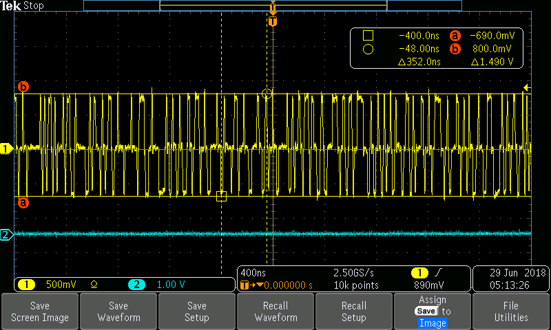
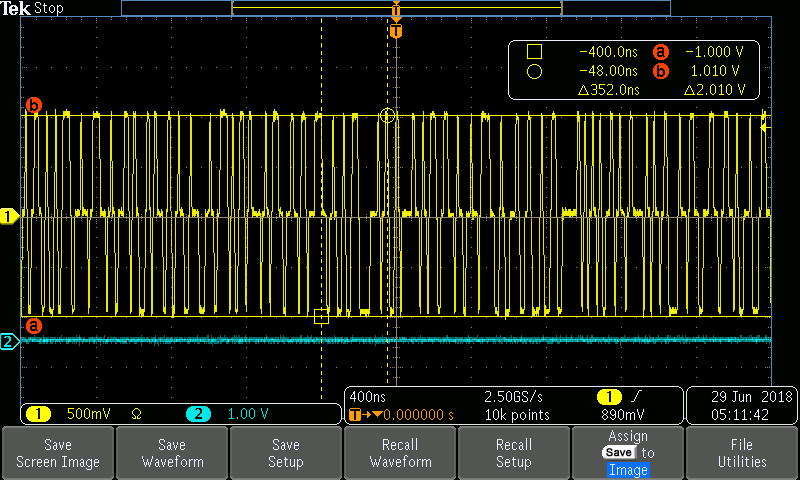
    I used an oscilloscope to verify.  The boards were all good at one time but then the signals got degraded.  We are fairly certain that it is ESD as we have taken many boards that were working and were able to damage them by numerous power cycles. I am using 4.87K for rbias.

    Try to measure resistance from 3.3V ethernet termination plane to ground.  Our failing boards measure around 200 ohms where a good board is 7000 ohms.  

    Failing Board Picture:


    Good Board Picture:

  • Thanks for the suggested TVS diodes. I am going to mock one up for testing.
  • Respected sir,

                         I am also getting resistance of 230 ohm between VCC and GND.  I was able to establish link (malfunctioning) by changing Rbais. But i am facing another problem. The voltage on TX-P and TX-N line is not symmetric. On TX-N line it is giving 1.08 V which is right. But on TX-P line it is giving voltage of 720 mV. They should be same. When i opened tracks by removing component on track and measured resistance with respect to ground it was giving 1K for TX-P and 42K  for TX-N. Can you please verify this with faulty board.  I am planning on populating second card and then testing this issue.

    Regards,

    Digvijay

  • Digvijay,

    From your measurement results between VCC and GND it sounds like you have damaged your MCU too. I have actually repaired all of my boards now by replacing the MCU's.

    Regards,
    Marc
  • Secondly the 20pf caps TX/RX pairs may be suspect in allowing outside sources of EMI from ground to enter the pins. Toshiba makes a tiny bidirectional TVS 20KV (DF2B5M4SL) pads on bottom/side wall. Forget about soldering them by iron, solder paste & hot air perhaps may work!

  • Check the ohms pin PB1 if using +VBUS from USB port, it may be that pin as we found was being compromised. That 230 ohms sometimes makes MCU run hot but not always, PB1 rail diodes are suspect.
  • I am not using the +VBUS. Thanks.
  • Perhaps other poster is ? odd to find caps on differential pairs can lead to ESD rail diode failure. Typically don't believe ESD 100v machine model occurs often or at all in humidity controlled environments. Air conditioning though it removes moisture from the air never seems to produce any static conditions that rise above table values.

    Seemingly the differential pair is being stressed from some other source perhaps the 3v3 bias source?