This thread has been locked.

If you have a related question, please click the "Ask a related question" button in the top right corner. The newly created question will be automatically linked to this question.

DRV8704: SPI code sample

Part Number: DRV8704
Other Parts Discussed in Thread: DRV8703-Q1, MSP430F2617, DRV8711, MSP430G2553, ENERGIA,
Hello, 
Our team builds an electric car to compete in the Shell Eco Marathon. As part of regulations, we are required to design our own Motor Controller as well. We decided to use the DRV8704 driver. We've designed our own PCB and now have to program it's operation using SPI controls. 
However, we've had lots of bugs with interfacing to this controller via an Arduino. I've attached the .ino file of the code that we've been using so far. We can't get the chip to respond no matter what. We're thinking about switching to a TI msp430 microcontroller. Do you know how we could program it? What would you recommend/ 
Would you happen to have a sample SPI code for the drv8704 chip that we could use for reference? or could you help us debug our current code. 
Thank you so much, 
-Rice Electric Vehicle team 

/*

* SPI interface for Motor
*
* This code controls DRV8704 motor driver. DRV8704 is SPI-compatible, and to command it, you send
* 12 data bits and 1 read/write bit.
*
* The circuit
* - SCLK: to SCK(ICSP-3) or digital pin 13
* - SDATI: MOSI(ICSP-4) or digital pin 11
* - SCS: 10
* - SDATO: MISO(ICSP-1) or digital pin 12
*
* created 31 Mar 2017 by Irene Zhang
*/

//include the SPI library
#include <SPI.h>

//pins used for the connection with the chip
//the other pins will be controlled by SPI library
//const int SS = 10;


//DRV8704's register addresses:
//const int CTRL = 0x00;
//const int TORQUE = 0x01;
//const int OFF = 0x02;
//const int BLANK = 0x03;
//const int DECAY = 0x04;
//const int DRIVE = 0x06;
//const int STATUS = 0x07;


//**** Configure the Motor Driver's Settings ****//
void setup(){
//set SS pin as an output
pinMode(SS, OUTPUT);
SPI.begin();
}

void control(int reg, int value){
digitalWrite(SS, LOW);
SPI.transfer(reg);
SPI.transfer(value);
digitalWrite(SS, HIGH);
}


void readData(int reg){
int val;
val = digitalRead(12);
Serial.println(val);
}

void loop(){
control(0, 1);
control(9, 1);
control(8, 1);
control(11,0);
control(10,0);
}

  • Hi Jose,

    Have you tried to read a register with a known default, such as 0x02 with 0x130 as the default?
    Have you compared the SPI transactions to figure 16 and 17 in the datasheet?
    Are you sure the SCS is correct? The code says SS is low during the transaction, but the device need a high.

    The MSP430F2617 is used to control a similar device, the DRV8711. Other devices like the MSP430G2553 have been used to control the DRV8703-Q1.
  • No, we haven't done those things. We will try again with a TI MSP430 microcontroller, and make the changes you suggested. 

    What IDE do you recommend using? Will Energia work? Is there an SPI library associated with it? 

    Thanks! 

    -Manuel 

  • Also: Quick question, the gate driver mentions several applications in the datasheet, like ATM machines, office automation machines, Factory automation and robotics, and Textile machines. But we don't see motor control in the sense of driving a car specified in the datasheet.

    Would this gate driver still work for our function of controlling the speed of a car? Would it be feasible to take an input pedal signal to a microcontroller, and control the speed of a motor using this driver?
  • Hi Jose,

    I have not used Energia, so I cannot comment. There should be a library available. Just make sure the SCS polarity and data/clock polarity matches the datasheet.

    Also: Quick question, the gate driver mentions several applications in the datasheet, like ATM machines, office automation machines, Factory automation and robotics, and Textile machines. But we don't see motor control in the sense of driving a car specified in the datasheet.

    Would this gate driver still work for our function of controlling the speed of a car? Would it be feasible to take an input pedal signal to a microcontroller, and control the speed of a motor using this driver?

    Yes, this application can work also. The DRV8704 EVM effectively does this with a 555 timer. Using a ADC to read a voltage and convert it to a PWM duty cycle can be done with a micro.
  • Oh great! The 555 timer is included inside the drv8704 gate driver, right? It is not something that we need to add in separately? 

    And thank you so much for your help! I've written a draft of the code. As soon as the flooding recedes and I can return to school, I will test it and update you. 

  • Hi Jose,

    The 555 timer is not inside the DRV8704; it is on the DRV8704EVM. If you need a 555 timer, it should be added separately. You may be able to PWM of the mcu instead of a 555 timer.

    Stay safe.
  • Hey Rick, 

    So we tried the SPI controls again. We tried reading a a known register (OFF, 0x02), and got no response. When we tried to read the known default addresses, we only received 0 as an output, always. 

    We used the Energia programming environment, and an MSP432 microcontroller. 

    So we send data using the MSB format right? Not LSB? 

    Do you know what could be wrong with our code or SPI interface? 

    /* This is the SPI code to control the DRV8704 gate driver.
    */

    //Include the SPI library:
    #include <SPI.h>;
    const int chipSelectPin = 40; //(update the actual chip select pin when you connect) //P2.7
    //NOTE: All the other pins (MISO, MOSI, and CLK will be controlled by the SPI pins.
    //Check your microcontroller datasheet to ensure which ones go where.

    //Let's program some register addresses! - a detailed guide can be found in page 20 of the DRV8704 datasheet. Please look it up!
    const int CTRL = B000; // Enable/disable motor, ISENSE amplifier gain set, dead time set
    const int TORQUE = B001; // Sets full scale output current for both H-bridges
    const int OFF = B010; // Sets fixed OFF time (decay time for PWM?) What happens if you increase/decrease this value?
    const int BLANK = B011; //sets current trip blanking time. This is the amount of time current is monitored for?
    const int DECAY = B100; //Mixed decay transition times, and slow/fast decay configurations.
    //0x05 is reserved
    const int DRIVE = B110; // controls OCP threshold, OCP deglitch time, Gate-sink time gate drive source itime, peak sink and source current
    const int STATUS = B111; //Tells you any errors/problems -Overtemperature, overcurrent, predriver faults.

    void setup() {
    pinMode(chipSelectPin, OUTPUT); //Set the SCS to an output. So when we want to access this chip we will output a HIGH.
    Serial.begin(9600); //begin serial communication, with 9600 baud rate. This will allow us to print and see what's going on.
    SPI.begin(); //I guess this just begins the SPI protocol.
    SPI.setBitOrder(MSBFIRST);//setting the order of the bits to most sig. bit first.
    //QUESTION: We have MSB first right?
    }
    void loop() {

    byte data = readData(STATUS); //read the data from the OFF register. This should output 0x130 as the default.
    Serial.println(data, BIN);
    delay(100);

    }

    byte readData(byte reg){ //input a register and this will read the data from that register.
    SPI.setDataMode(SPI_MODE0); // Clock polarity is 0 (clock is idle when low), and clock phase is set to 0 (data shifted using falling edge)
    //QUESTION: Is Clock polarity 0 or 1? I can't tell.
    digitalWrite(chipSelectPin, HIGH); //Write a high to the CHIP select pin to enable it
    //QUESTION: Which one comes first? enabling the clock, or selecting the pin to high?
    byte readData = SPI.transfer(B1000 + reg, BIN); //We need to transfer a 1 followed by the 3 bits of the address. How do we do this?
    delay(100);
    digitalWrite(chipSelectPin, LOW); //to disable the pin
    return readData;
    }

    Best, 

    -Manuel 

  • Hi Manuel,

    Please capture the transaction on a scope, and compare it to the datasheet.
  • Yes, good idea. The building that houses the high-quality scopes with SPI readings is currently flooded and closed until next Tuesday. 

    As soon as it opens we will try this. But meanwhile we have ordered a digital potentiometer that we'll try to program using SPI controls for practice. 

    Best, 

    -Manuel 

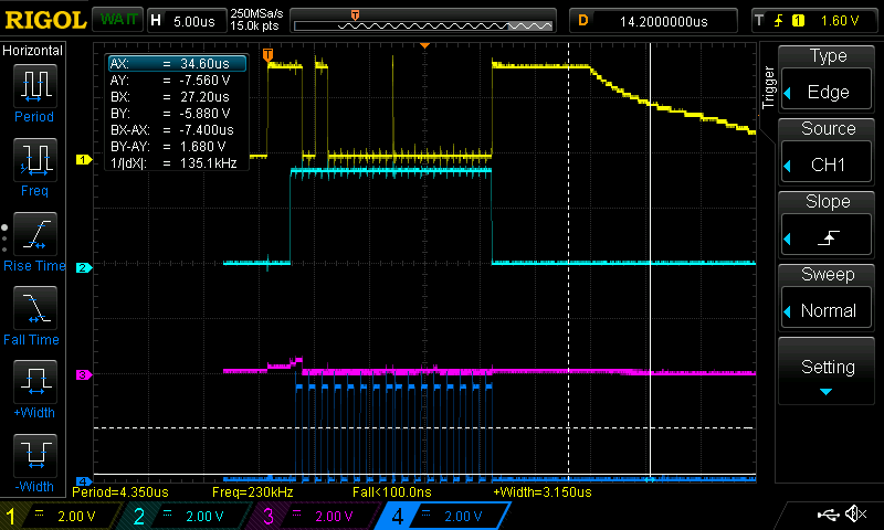
  • Hello. I have the same problem. No MISO signal, no matter what MOSI is. For example, reading register 2:

    I use DRV8704EVM.

  • Hi Jose,

    Have you made any modifications to the EVM? If so, what have you done?
    When trying to read MISO, what is the DRV8704 in sleep mode?
  • No, we haven't done any modifications. When we try the SPI protocol, we usually unplug the rest of the pins connected to the board. 

    Taking it out of sleep mode is a great idea! I never paid attention to that.  

    Otherwise, if we sent a PWM signal to certain pins of the gate driver, could we control the speed of our motor, without configuring any settings with the SPI interface? If possible, our team would like to start testing the motors without worrying about the SPI interface for now. 

  • Hi Jose,

    "Otherwise, if we sent a PWM signal to certain pins of the gate driver, could we control the speed of our motor, without configuring any settings with the SPI interface? If possible, our team would like to start testing the motors without worrying about the SPI interface for now. "

    Yes, the device is enabled and will respond to PWM inputs once nSLEEPn is set to a logic high and RESET is set to a logic low. You may not obtain the desired current because the default gain and torque settings may not be optimal for your motor.

    It is recommended to set the SPI registers for your application.
  • No modifications to EVM. EVM is powered by a 11.1 V battery. Green status LED is on and red FAULT LED is off. I connected 4 wires to MSU (Teensy 3.2): SCS, SCLK, SDATO as MISO, SDATI as MOSI, and directly 3.3V to nSLEEP. The board is not in a sleep mode as the motors work fine.
  • Hi Priba,

    Are you still having problems with the SPI transactions?
    It is recommended to try to read a register with known data.
    Do you have a common GND between the MSU and the EVM?
  • I do. There is a common ground. I tried reading registers 0, 1 and 2 but no MISO activity anywhere. I checked timing constraints and didn't find a problem there. In fact I first developed my PCB based on DRV8704 and could not use SPI so I bought an EVM. I suppose I do something wrong, but could not find what. I can send you a picture of the boards and connections.
  • Hi Priba,

    Please send the pictures. Thanks.

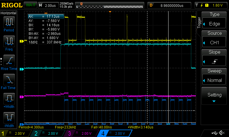
    Also, please provide the scope captures of the 4 SPI signals.
  • Hi Priba,

    Also, can you provide function definitions of SPI read write .

    Thanks
    Abhishek
  • Analyzer:

    Scope for the same run:

    The same, but a different time scale:

    Arduino code:

    #include <SPI.h>
    #define SS_PIN 10

    void setup()
    {
    pinMode(SS_PIN, OUTPUT);
    Serial.begin(115200);

    SPI.begin();
    digitalWrite(SS_PIN, LOW);

    byte data[] = {0b10100000, 0b00000000};

    SPI.beginTransaction(SPISettings(1000000, MSBFIRST, SPI_MODE0));
    digitalWrite(SS_PIN, HIGH);
    SPI.transfer(data, 2);
    digitalWrite(SS_PIN, LOW);
    SPI.endTransaction();

    Serial.println("Read:");
    Serial.print(data[0], 2);
    Serial.print(" ");
    Serial.println(data[1], 2);

    SPI.end();
    }

    void loop(){}

    The boards:

  • Hi Priba,

    Thanks for the picture and the scope captures. Can you confirm J12-Pin1 is floating? It should be connected to 3.3V.

    Connecting J12-Pin1 to 3.3V will provide the voltage needed for SDO. As an open drain output, an external pullup resistor is required.
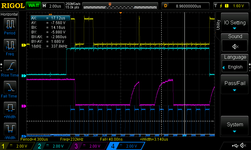
  • I confirm. And, yes, that was the problem! Now I got the right content of the register 2:

    Thank you for your help. TI delivers excellent product documentation and support.

  • Great!! Good luck moving forward.