This thread has been locked.

If you have a related question, please click the "Ask a related question" button in the top right corner. The newly created question will be automatically linked to this question.

CCS/DRV8323: update from DRV8305 to DRV8323

Part Number: DRV8323
Other Parts Discussed in Thread: DRV8305, CSD88599Q5DC, MOTORWARE

Tool/software: Code Composer Studio

Hello everyone, I am again with a question on DRV8323.
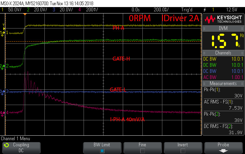
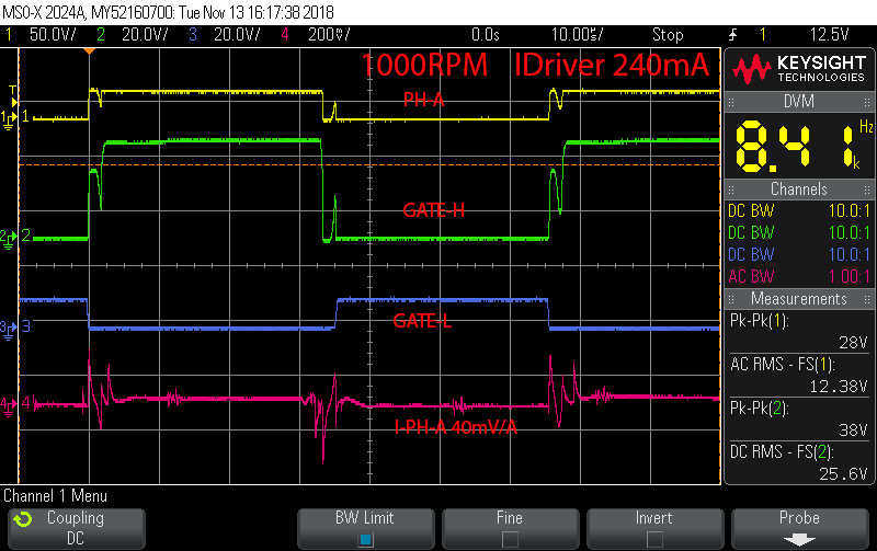
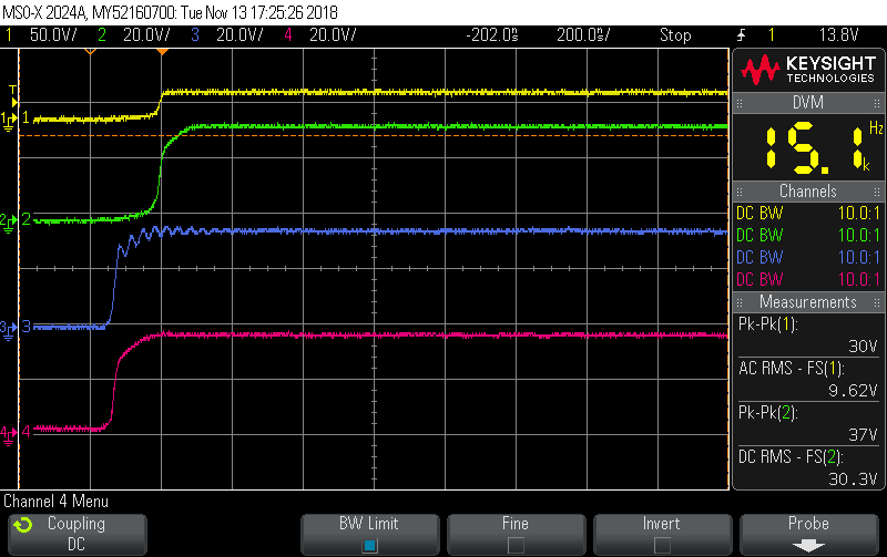
Driver output  looks like this 

I can not understand where these short signals come from. At the input of the driver, the signal is not interrupted.

Green middle point of the bridge. blue gate high FET.

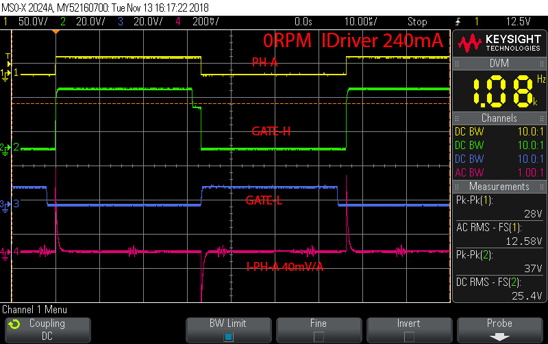
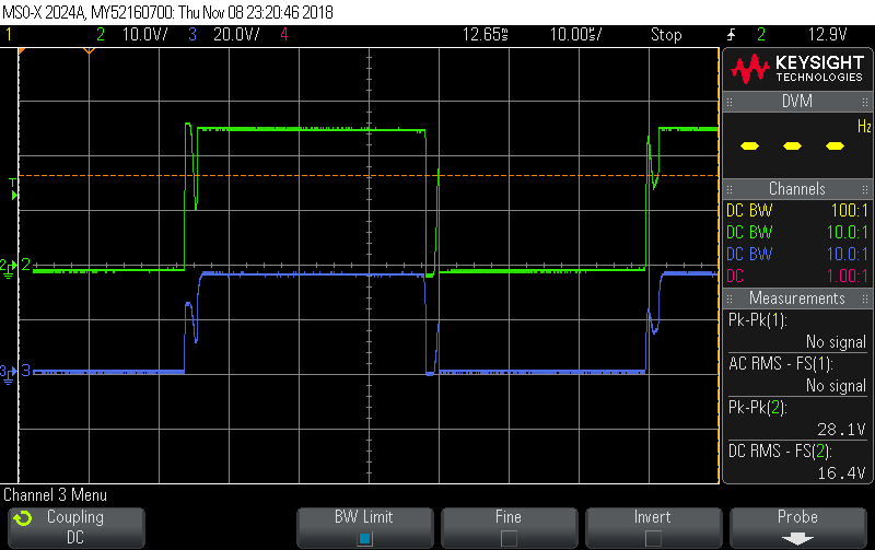
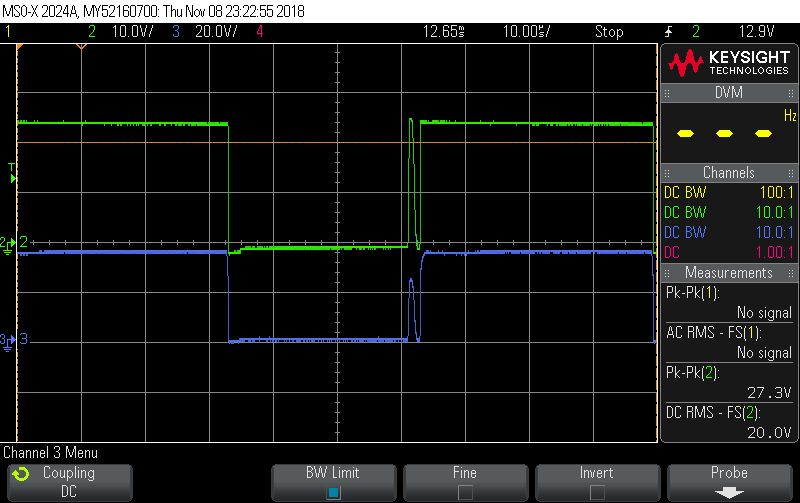
The output of DRV8305 looks better.

Ch2.

  • Andrew,

    Sorry for the delay here.

    Is this occurring on your own board or the EVM?

    What FET is being used and can you send me a picture of your register configuration?

    Regards.

    -Adam
  • I use CSD88599Q5DC. I use DRV8323RH. I tried IDRIVE = Hi-Z 240
    IDRIVE = 75 kΩ to DVDD 520, IDRIVE = 18 kΩ to DVDD 1140, IDRIVE = to DVDD 2000.

    U7 DNP

    R15,R16 = 0R.

  • Andrew,

    Was the result the same if you used lower iDrive vs. higher iDrive? This could help us rule out an iDrive issue. The images shown, which iDrive setting was used. If iDrive is too high, it could cause other phases/nodes to unintentionally turn on which could cause this issue to appear.

    Another possible issue is that the parallel FET architecture is causing this issue. Could you remove the gate resistors on LS and HS for either U6 or U7 and see if this behavior is any different?

    Regards,

    -Adam
  • The second transistor is not installed.

    Switching in one channel is induced on the gate in another channel?
    Does Switching open a high transistor in another channel and then the driver closes it?

  •  I looked three channels in the gates. In one of the channels visible fluctuations. 0-RPM. IDRIVE - 2A.

  • Andrew,

    Please send us your remaining schematic, if concerned, please email it to adam(dot)sidelsky(at)ti(dot)com.

    Regards.

    -Adam
  • We have a standard scheme.  :)EVO BLDC 6050C.PDF

  • Andrew,

    What is your peak and continuous current per phase?
    We notice a small amount of VM capacitance near the DRV, can you probe VM near DRV with scope?
    Also please probe nFAULT same time.
    Could you share scope images of the input while the motor is spinning at 1000RPM?
    The 1000RPM images shown, are these during spin up or with the motor consistently spinning 1000RPM?
    Would you be willing to share the layout?
    What is the application here? Are the output wires long? Are the FETs far away from the DRV?

    Regards.

    -Adam
  • Thanks for the advice,

    I watched. nFAULT - everything is clean. We want current up to 70A.
    I set GAIN to 40V/V and #define USER_ADC_FULL_SCALE_CURRENT_A (82.5)
    I set PWM frequency to 60-80KHz. fluctuations gone. :)

    How set the dead time between phases in MotorWare?
    Is now the dead time depends on the frequency of the PWM?

    Where can I find recommendations (formulas) on the PWM frequency for motors with a small inductance.

    thank
    Andrew.

    PS:

    I returned to PWM to 15 KHz, reduced two define to 0.5.

    The signals have become readable and beautiful.  :)


    // # define HAL_PWM_DBFED_CNT 1
    #define HAL_PWM_DBFED_CNT (uint16_t) (0.5 * (float_t) USER_SYSTEM_FREQ_MHz) // 2 usec


    //! \ brief Defines the PWM deadband rising edge count (system clocks)
    //!
    // # define HAL_PWM_DBRED_CNT 1
    #define HAL_PWM_DBRED_CNT (uint16_t) (0.5 * (float_t) USER_SYSTEM_FREQ_MHz) // 2 usec


    Now I repeat all the tests.
    Maybe something else forgot and missed.

    :)

  • I did the first tests. A beautiful signal in the GATE and phase does not mean that the motor is working well. :(

    I made a speed comparison regarding the delay. And back to delay 2us or 3us.

    I did not expect that with "field weakening" a big difference in speed. To change the direction of rotation with the "field weakening" with great acceleration is generally impossible.

  • Andrew,

    I'm sorry for the delay, I was on vacation. Any update here?

    Regards,

    -Adam
  • Hello Adam,

    dead zone - figured out.
    For CSD88599Q5DCT I reduced to 0.2uS. The difference between the normal mode and the "field weakening" has become much smaller.
    I have a question. According to the parameters of MotorWare.
    1. I returned to GAIN 20V /V and set
    #define USER_ADC_FULL_SCALE_CURRENT_A (165) // Rsh 1mR

    I have a Rsh 1mR, 5W that will allow the controller to load up to 70A RMS. For sine, the peak current will be 100A. The current through the motor phase is not the RMS current. :) Resistances allow 5x overload and I have good cooling. (water)

    I have a 50A, 600W motor. Alas, I do not know what the current RMS or peak, and I do not know the maximum through.

    I set
    #define USER_IQ_FULL_SCALE_CURRENT_A (100.0) // peak Rsh
    and limited
    #define USER_MOTOR_MAX_CURRENT (70.0) //peak motor

    I managed to load the motor up to 600W - 1000W.

    In many TI examples, "#define USER_IQ_FULL_SCALE_CURRENT_A" is set to half of #define USER_ADC_FULL_SCALE_CURRENT_A
    In my case, this would be dvr8323 - 140A / 2 = 70A.

    Can someone from the TI make comments of their choice.
    #define USER_IQ_FULL_SCALE_CURRENT_A - RMS <> peak ????
    #define USER_MOTOR_MAX_CURRENT RMS <> Peak ???

    Thank.
    Andrew.

  • #define USER_ADC_FULL_SCALE_CURRENT_A (165) // Rsh 1mR

    suggests your hardware is measuring -82.5A (0V at ADC) to 82.5A (3.0V at ADC)

    Is this correct?

    If so, you should set

    #define USER_IQ_FULL_SCALE_CURRENT_A (82.5)

    #define USER_MOTOR_MAX_CURRENT

    should be set to the peak IqRef_A  command that you want the speed controller to saturate too. This is not a hardware limit, but a limit on the input to the torque controller (when you are using the PI speed controller).

  • Are you sure?

    For example in the project www.ti.com/.../boostxl-drv8323rs.
    set.

    #define USER_IQ_FULL_SCALE_CURRENT_A (20.0) // BOOSTXL-DRV8323EVM = 20.0 A

    //! \brief Defines the maximum current at the AD converter
    //! \brief The value that will be represented by the maximum ADC input (3.3V) and conversion (0FFFh)
    //! \brief Hardware dependent, this should be based on the current sensing and scaling to the ADC input
    #define USER_ADC_FULL_SCALE_CURRENT_A (23.57) // BOOSTXL-DRV8323EVM = 23.57 A as it uses 20V/V (DEFAULT MODE)

    20A is the linear range for DRV8323.

    In my case it would be 140A.
    But, 140A my board just can not, but 100A peak is possible. :)

    I count on 70A peak. Since I do not know the peak moment for the motor. I will limit the current for the motor to 50A. My controller will turn out with low power. :(
  • the IQ needs to be equal or greater than (but greater than doesn't buy you anything) half the ADC value.

    In the variables you just posted the ADC_FULL_SCALE_CURRENT is telling the software that there is a full range of 11.785 Amps.
    The IQ value needs to be at lease 11.785, so normally you would just round up to (12.0)

    the USER_MOTOR_MAX_CURRENT is not a current limit for the motor. Again, it is a limit of the speed controller output, which is an IqRef command to the torque controller.
  • #define ADC_FULL_SCALE_CURRENT (23.57) ---- not 11.785
    #define USER_IQ_FULL_SCALE_CURRENT_A (20.0) - 20A Peak. not 12A
  • #define ADC_FULL_SCALE_CURRENT (23.57) means it is measuring +/- 11.785 max.
    If you have a 20A peak motor you need to change this scaling to measure something more like +/- 24A

    #define USER_IQ_FULL_SCALE_CURRENT_A should be set to (12.0) or greater (and greater doesn't buy you anything).
  • In my case, having a motor peak 50A.
    must be set #define USER_IQ_FULL_SCALE_CURRENT_A to 25A or more. but not more than 70A. Since 140A is the entire linear range.
    But, it does not really agree with an example. www.ti.com/.../boostxl-drv8323rs
  • I'm just telling you how USER_IQ_FULL_SCALE_CURRENT_A should be set, based on USER_ADC_FULL_SCALE_A.
    It has nothing to do with the motor you are using, just the inverter hardware.

    I agree that whomever used MotorWare to make this DRV8323 example did not set it up like I would have. I'll also say that having the IQ_FULL_SCALE_CURRENT to some larger number isn't necessarily wrong, but it doesn't do any good either.
  • TI cannot give a clear answer? Is it need to respect the ratio of 2 and more for the parameters USER_IQ_FULL_SCALE_CURRENT_A USER_ADC_FULL_SCALE_A? For myself, I decide. But, I see that custom need recommendations from TI how to transfer MotorWare to the custom hardware. :) :) :)
  • Andrew,

    I don't know how to be more clear and I've repeated myself multiple times. This is documented in the code comments and the InstaSPIN User's Guide section 4.1

  • Thank. In sight, I forgot what is written in User's Guide 5.1.3 IQ Full-Scale Current.