This thread has been locked.

If you have a related question, please click the "Ask a related question" button in the top right corner. The newly created question will be automatically linked to this question.

DRV8412: bypass capacitor for dc motor

Part Number: DRV8412

We are currently using DRV8412 for driving brushed dc motor driving and we were planning to use bypass capacitors which is always recommended.

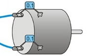
When we add two capacitors of 0.1uF from motor terminal to chassis, we can see ringing in the pwm signals.Is bypass needed for this driver?If yes then what value should I select the cap?

  • Abhi,

    Where is the chassis? I mean is it connected to motor drive board ground or is it floating?

  • The chassis is connected to GND of motor drive board.

    1> If we hook up the motor directly to the power supply then we can see the noise on the oscilloscope ?I assume this noise is due to brushes .If we add 0.1 cap the signal is clean.(Attached Image 1 for motor noise).

    2> Using DRV8412 (pwm at 32Khz) we can see some ringing (more than +/-5 Volts)Attached image 2 .It is without motor connected.How can we reduce this ? Is it due to layout ?

    3> If we connect motor with  capacitor of 0.1uF two caps from each terminal to Chassis(which is connected to Gnd) we see high frequency ringing.Attached Image 3


  • Abhi,

    The switching FET circuit is similar as a buck converter. To reduce the ringing, please put a ceramic capacitor near the High side FET's drain and low side FET's source. For DRV8412, please put a 0.1uF~1uF ceramic capacitor close to IC's PVDD_x and GND_x pin.

    Which one is image 3?
  • For DRV8412, please put a 0.1uF~1uF ceramic capacitor close to IC's PVDD_x and GND_x pin."

    Currently we are using 0.1uF cap between PVDDx and GNDx and is very close to DRV8412 . Should we increase the cap value ? May I know the reason for this ringing.

    "Which one is image 3?"

    If we connect motor with  capacitor of 0.1uF two caps from each terminal to Chassis(which is connected to Gnd) we see high frequency ringing.Do we need to connect this capacitiors?

  • Abhi,

    The parasitic inductance in input capacitor; switching FET loop could cause the switching node ringing. Detail analysis can be found in: www.ti.com/.../slyt465.pdf; www.ti.com/.../slyt682.pdf and www.ti.com/.../slpa009a.pdf

    I would think the 0.1uF on chassis provides a current path for common mode noise. When the motor winding terminal voltage jumps, the common mode current can pass to the chassis through the parasitic capacitance between the winding and chassis. 0.1uF cap on chassis can provide a current path and let that common mode  current back to motor driver board ground.  So, I would add the 0.1uF capacitor from chassis to motor drive board ground. This is just my opinion.

  • Wang,

    We tried connecting different capacitors from 0.1uF to 1uF but there doesn't seem much difference. Do you think we should add a resistor series( Rboot ) with the capacitor ?

  • Abhi,

    The switching node ringing is related to the switching FET and input capacitor loop area (ceramic capacitor close to IC's PVDD_x and GND_x pin). Not the 0.1uF or 1uF to the chassis.

    If change capacitor for IC's PVDD_x and GND_x pin doesn't help, only thing we can do is reducing the switching FET turn-on speed. Would you try adding a 3ohm or 5ohm series resistor on BST_x capacitor?