This thread has been locked.

If you have a related question, please click the "Ask a related question" button in the top right corner. The newly created question will be automatically linked to this question.

DRV8870: H-Bridge not driving the motor as expected

Part Number: DRV8870

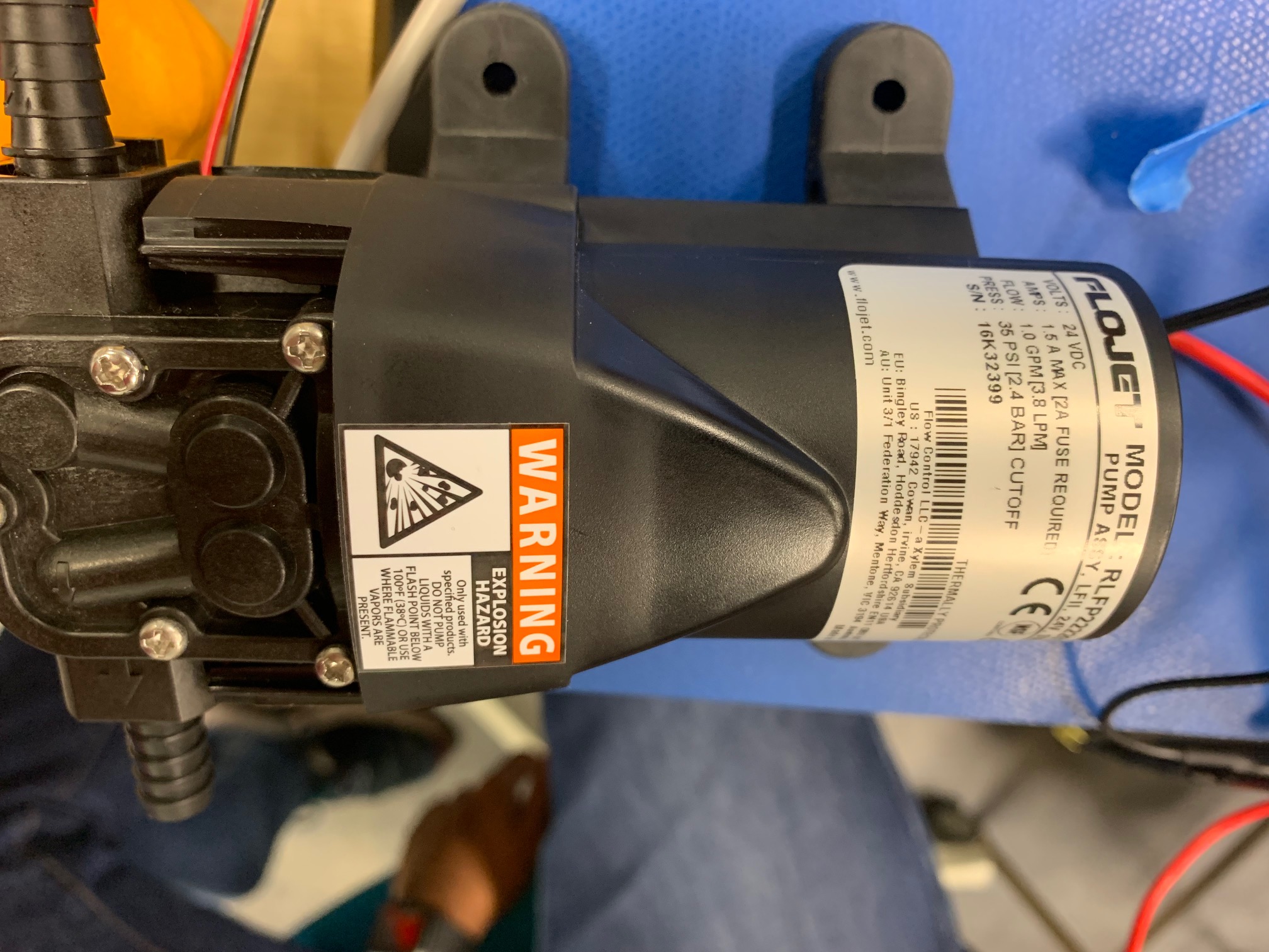
We are using the DRV8870 to drive a simple 24V DC Brush Motor.  Actually we are using it in 9 places on one board.  

I have attached my schematic.

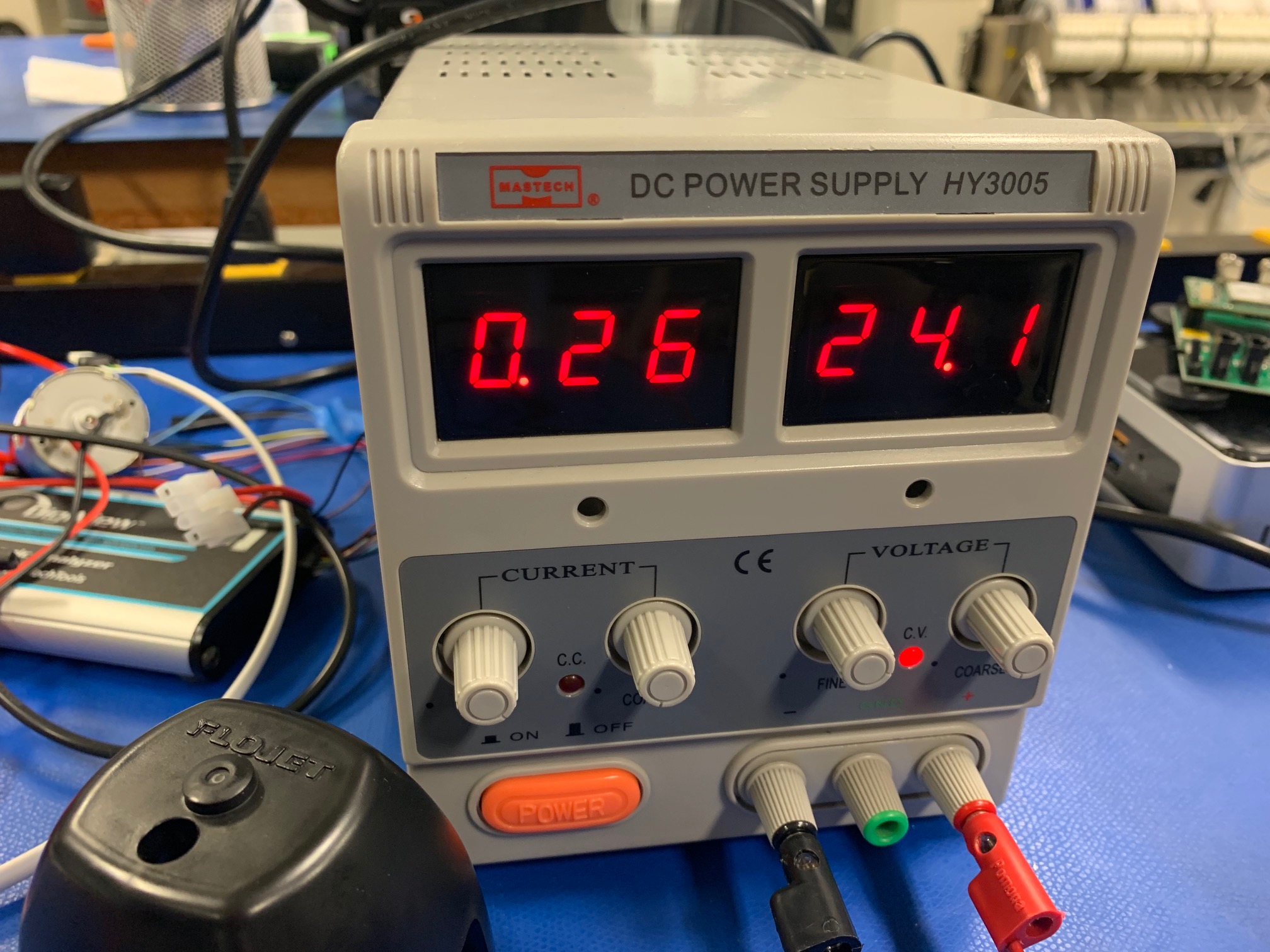
If I run my motor directly from a bench top power supply, at 24V it draws 240mA. 

When I set IN2 HIGH and IN1 LOW I would expect to see the motor run in the same way. 

The motor just hums... It draws the same current as if it was running, but it does not move. 

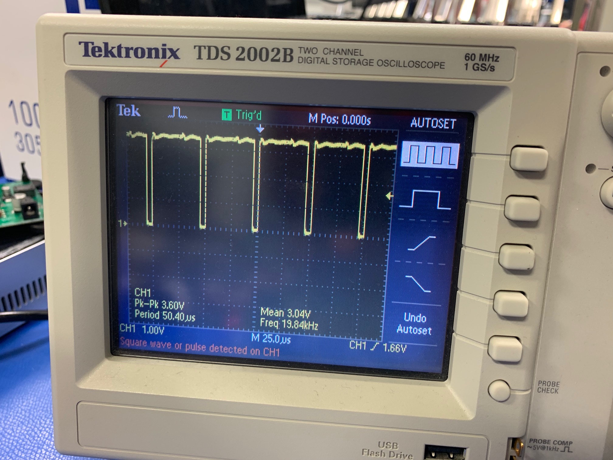
If I set IN1 LOW and PWM IN2 with 20KHz at 90% duty cycle the motor just hums and draws the same current.

We are verifying the 90% dutycycle PWM being applied to IN2 with our Oscilloscope.  I have attached a picture showing this.

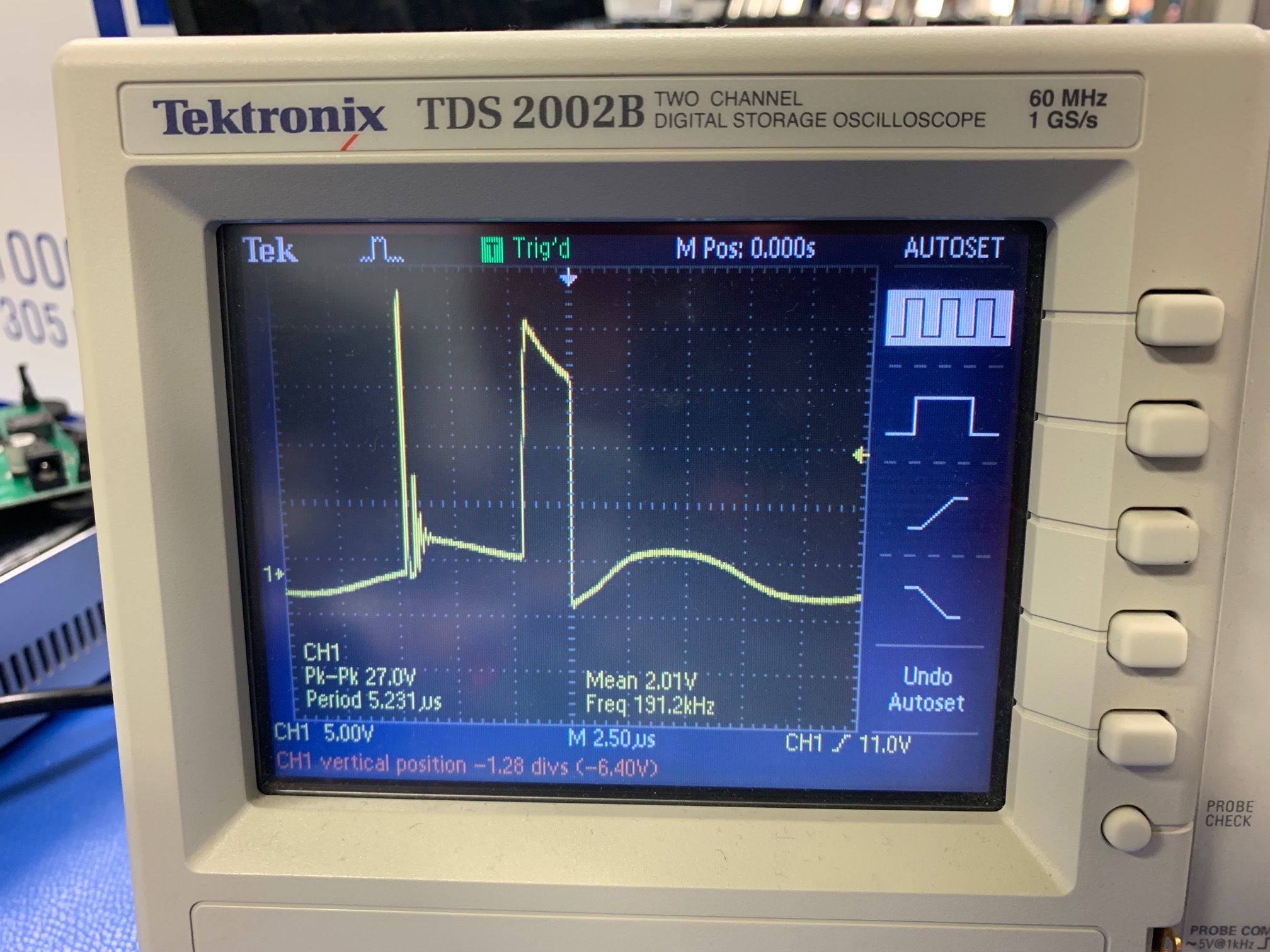
I have also attached a picture of the Oscilloscope showing the wave form when connected directly across the motor. 

We increased the bulk capacitance from 68uF to 1000uF.  No improvements.  We increased it further to 2000uF, still no improvements.

We added 2 large 22uH toroid inductors on the two motor leads still no improvement. 

We repeated the tests.  If start with 90% duty cycle the motor starts to spin as expected. 

We can ramp from 90 to 100% it works. 

If we start at 100% it does not work.  The motor runs at approximately 20%, even though it should be running at 100%.If we stop, then start at 50% and then jump to 100% it will work.

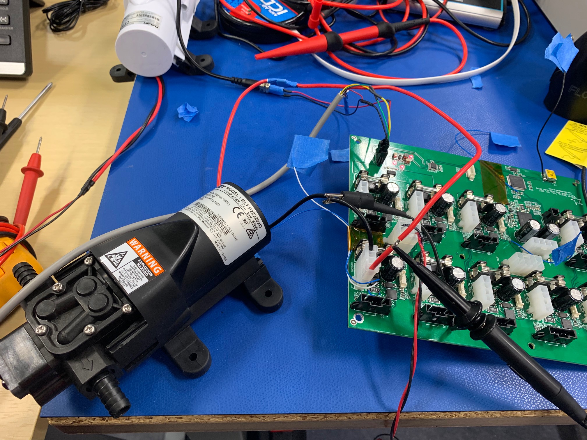
See attached picture showing the inductors in place.  I have also done this same testing with one other simple gear motor.  Same results.

Can you please help me understand why this is happening?  It doesn't make sense to us why at 100% NO PWM, simply turning IN2 HIGH and IN1 LOW, why our motor doesn't run 100% speed? 

Did I miss something?  We have replaced our Isen resistor with a jumper.  Still no improvements.  Please help!  Thank you!


4174.Schematic Prints.PDF

  • Jameel,

    I would think the output current triggers OCP according to your description and waveform:
    1. The "connected directly across the motor" waveform shows the voltage drop very quick. That indicates the motor inductance is not higher enough which may not hold the winding current below the OCP threshold.
    2. The "connected directly across the motor" waveform shows the pulse is about 2us. That is similar as the tocp deglitch timing.

    If 24V is directly added to the motor when motor stops, there is no EMF against the input voltage and reduce the winding current. So, the OCP can be triggered. After motor spins, the EMF can reduce the winding current ramp up and avoid OCP.

    50% duty cycle can start normally. That tells us OCP may not be triggered if the winding inductance is doubled. And also tell us the 22uH series inductor could be much less than the motor inductance. That 22uH inductor can take much higher current than 1A. So, you can reduce the inductor current rating and put more wire turns to increase the inductance value to motor inductance level. So, we may avoid the OCP issue and verify the concept.

    I also think starting with a low duty cycle could be a good solution.
  • Hello Wang,

    Thank you for helping me with this.

    We put QTY 2, 22uH inductors in series on each side of the motor.  You can see the picture below.

    Now we have 44uH on both sides.  The motor is operating as expected.   I can start the motor from 0 to 100% without any problems now. 

    Having these 4 massive inductors on my board is not an acceptable final solution. 

    Normally we never have any inductors on my motor drive circuits. 

    What can I do to eliminate these?  I don't know why we are triggering OCP.  My Isen resistor is set to 0.2 Ohms.  Can we just disable OCP?  If so, how do we disable OCP (Over current protection)?

    If you say, sorry, you must have these inductors, what is the smallest inductors we can use on my board?  My goal is to handle up to 24V 2A continuously. 

    If I use other motor drivers I have designed in my office, they do not need these inductors.  Why?  Was this DRV88703 a bad choice?

    Thank you so much for your help.  I hope you can help me improve my design so that I can keep using these DRV88703 parts.  We will need 9 of these per board.  EAU is over 100,000 boards... which gets us close to 1 million parts in 2019.

  • Jameel,

    Motor drive winding is an inductor. After apply a voltage on it, the current will go up. DRV8870 OCP current threshold is fixed and deglitch time is fixed. To avoid triggering OCP:
    1. as you mentioned, reduce the sense resistor value. But, please re-check the current control value.
    2. According to motor picture, the winding current rating is only 1.5A. The inductor size could be much smaller than what you have now.
    For example: you put "2A 47uH inductor" in google search, you could find a lot of inductors. For example: www.digikey.com/.../71
    3. I still think duty cycle soft start would be good.
  • Hi Wang,

    Do you have another drive chip you can recommend that will not require these inductors?
  • Jameel,

    Motor cannot start could be caused:

    1. The motor cannot generate enough torque at DRV8870 OCP current level.  This is not the case, the motor 1.5A maximum rating current is lower than DRV8870 3.7A OCP threshold. 

    2. The winding current goes up too quick to trigger the OCP and average winding current or motor torque can not make the motor spin. This is the issue we have.

    Before motor spin, the delta I = Vin x Tocp / L. Vin is 24V; L is the motor winding inductance. To get a higher average motor winding current:

    a. Find a higher tocp part, this could cause a higher peak current. The motor is 1.5A maximum rating current. 3.6A is higher enough and reasonable. I don't want to see much higher peak current due to longer OCP deglitch time.

    b. Reduce the total cycle time, find a short toff part. So, let the driver try to hit OCP more frequently. It also seems not a good and reliable solution.

    Overall, I would think putting a series inductor should be a correct solution.