This thread has been locked.

If you have a related question, please click the "Ask a related question" button in the top right corner. The newly created question will be automatically linked to this question.

DRV8332: Bootstrap Diode and UV Thermal Failures

Part Number: DRV8332

Hello,

We are using the DRV8332 to drive a 28V BLDC motor for an EMA application and are looking for guidance regarding two failures we have experienced:

1) We have followed the reference design and are using 0.1uF, 100V bootstrap capacitors with close placement to the IC pins. We have observed failure of the bootstrap diode (reading open) on phase B (checked with diode tester from GVDD_B to BST_B). Using 0.1uF, we see failure after prolonged use (~Tens of hours). As an experiment, we increased the value to 0.22uF and saw immediate and identical failure. This seems to indicate damage to the bootstrap diode due to increased in-rush current through the bootstrap cap (the datasheet mentions as much, recommending a series R for larger cap values). Do you have guidance on bootstrap cap value selection? Especially based on PWM frequency or load current if there is such a dependency or recommendation?

2) We have also seen failures at hot temperatures (~85C Ta) where the unit reports numerous UV faults, eventually damaging the high-side FET and shorting power to ground through the IC. Based on note 9.2.1.2.2 Current Requirement of 12 V Power Supply, the data sheet suggests that the 12V current supply requirement may "increase significantly" at higher temperatures, e.g. >125C. Can you elaborate on what "increase significantly" means? By how much? At what temperatures? Is there a curve or relationship for current vs temp that can be deduced based on load current? Our load current has a peak of 10A and we are driving 2x DRV8332's from a single 12V switching regulator that is capable of 500mA. The guideline seems to indicate that it should maximally be designed for 10% of the load current which would mean 0.1*10A*2 = 2A (up from 100mA??), is this correct?

Thanks,

- Victor

  • We urgently need to resolve these two issues. Any help would be greatly appreciated!

  • Hey Victor,

    Let me get back to you on these two questions. The experts on this part are out of office, so please expect a little delay.
    For the first question, what is the pwm frequency you will be using?

    Sincerely,
    Sanmesh U.
  • Hi Sanmesh,

    Thanks for the reply. Understood. Currently, the PWM frequency is set to 61.3 kHz.

    - Victor
  • For question #1:
    The 100nF recommendation allows operation to 10kHz. At 61kHz, 47nF should be plenty. If you want to lower inrush current further, a 33nF cap may also work. Measure the Vgs when driving the outputs (BST_x – OUT_x) high. The desire is to keep the voltage above 9.5V.

    For question #2:
    Please allow till early next week to confirm this for sure, when our expert comes back from vacation.

    Also, for extreme temperature applications, I would suggest looking at the DRV8332-HT (www.ti.com/.../description).
  • Hi Sanmesh,

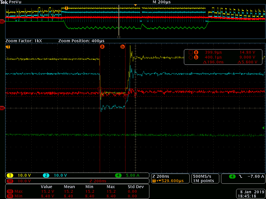
    Thanks for the information. We will test with the 33nF caps and see how it performs. Measuring BST_A to OUT_A it looks like it stays above +10V at max PWM:

    BST_A (yellow), OUT_A (blue), BST_A - OUT_A (red), OUT_A current (green)

    As for the DRV8332-HT, it looks like though it is rated to higher temperatures, it has much higher Rds on and lower rated peak and continuous current than the DRV8332. It doesn't look to be able to support a 10A peak current needed for our application.

    Looking forward to more information on thermal performance.

    Thanks,

    - Victor

  • Hey Victor,

    Regarding your question "The guideline seems to indicate that it should maximally be designed for 10% of the load current which would mean 0.1*10A*2 = 2A (up from 100mA??), is this correct?":

    Answer: this is correct. However if the peak current doesn't happen at the same time for both drivers, you can scale the LDO current to handle the peak for just one driver.
    Also, if the peaks are small enough in time scale, it would be possible to use larger bulk capacitors to handle the peak current demand while keeping the 12V regulator smaller to handle the RMS current.

    Let me know if this answers your question.

    Sincerely,
    Sanmesh U.
  • Hi Sanmesh,

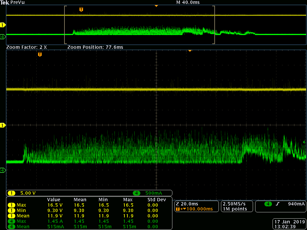
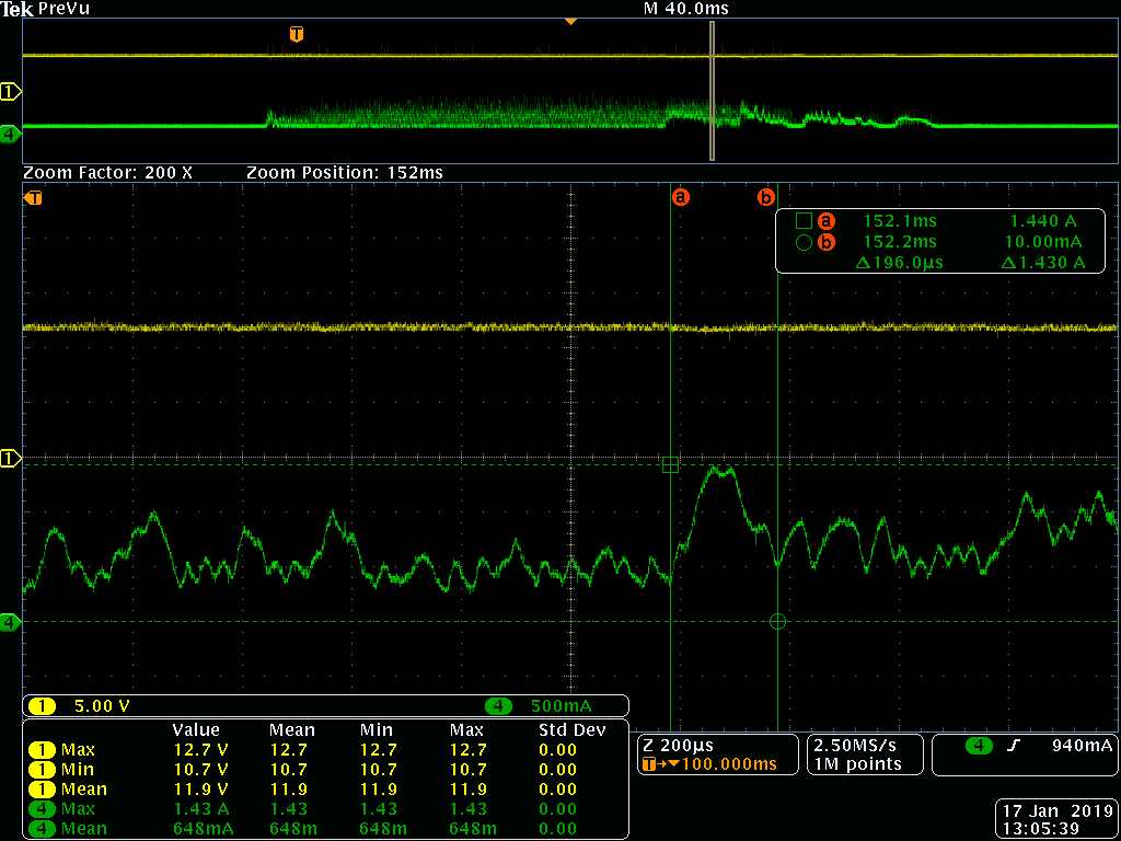
    Unfortunately we need to be able to drive both motors simultaneously. We have about 100uF of bulk capacitance on the +12V rail but that doesn't appear to be adequate to meet the instantaneous current requirement. As an experiment, we disconnected the on-board regulator and powered the +12V from a bench supply set to 2A. We also changed all the bootstrap caps to 33nF. Here is a plot of the current trace (green) and voltage (yellow) commanding both drivers at the same time at room temperature (25C):

    From the trace, we see a max current of 1.45A. This doesn't seem to agree with the application note of 50mA since this is at room temperature. Does this look like normal behavior? This is well beyond what has been specified by the datasheet. Do you recommend any other mitigation?

  • Hey Victor,

    1) The 50mA current at room temperature is 12V Vdd current with no motor load. At 10mA motor load, the Vdd current will be much higher.
    2) Unfortunately, other than the bulk capacitance on Vdd, there is no other solution to lower current requirement of 12V Vdd.

    If this is a problem, I can see if we can suggest an alternative part with lower current requirements
  • I'll mark this as resolved for now. But please, if you have any follow up questions on this topic, reply to this thread.
  • Hi Sanmesh,

    Is the Vdd current dependent on PWM frequency as well? Does the current requirement increase by relying on the cycle-by-cycle current limit?

    - Victor

  • Victor,

    Yes in both cases.

    Regards,

    -Adam