This thread has been locked.

If you have a related question, please click the "Ask a related question" button in the top right corner. The newly created question will be automatically linked to this question.

DRV8824: DRV8824 can not driver the motor

Part Number: DRV8824

Dear TI:
    My customer used DRV8824 for a step motor driver, there are output waveform in Aout and Bout, but the motor can't rotate.

    DRV8824  peripheral circuit configuration:  nReset, nSleep set to High, Mode, DIR, Decay Set to Low, Step is 50KHz 50% duty PWM. Fault pin is High.

    Customer used another solution A4988, the motor can work normal. Please help to check what may cause the motor to fail to rotate? 

    Thanks!

    1, Aout1 and Aout2 waveform:


  2, AOUT1 and BOUT1 waveform:
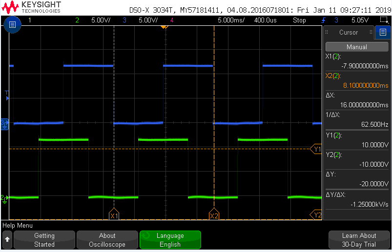
 

    3, STEP waveform:


   4, Schematic:


  • Hi Eric,

    The outputs are toggling as expected, but no current regulation is observed. If the current limit is reached in Image 1 (AOUT1 and AOUT2), the output at 12V should toggle between 12V and 0V while the other output should remain at 0V.


    If the customer has a current probe, please capture the currents in the motor coils.
    Please capture the voltages on the ISENA/B pins.
    What are the motor specification (V, R, I, L)
  • Hi Rick:
    Customer set R20/R21 to 0.5ohm,the motor still can't rotate. And customer said the motor current is only 20mA.
    So when mode0,1,2 set to "0,0,0", are the output waveform of AOUT1/AOU2/BOUT1 correct(duty cycle and sequence )?
    I think peripheral configuration are no problem, and the fault pin also output high level, and it doesn't look like it's current limited.
    Could it be the wrong output connection between DRV8824 and motor? I will visit customer tomorrow or the day after tomorrow, can you give me more advice?
    Thanks!

    Regards!
    Eric Shen
  • Hi Eric,

    So when mode0,1,2 set to "0,0,0", are the output waveform of AOUT1/AOU2/BOUT1 correct(duty cycle and sequence )?
    The output waveform looked correct if the motor is not connected.
    If the motor is connected, the outputs should toggle between steps. If the current limit is reached in Image 1 (AOUT1 and AOUT2), the output at 12V should toggle between 12V and 0V while the other output should remain at 0V.

    Can you get a scope capture of the ISENA and ISENB voltages while the STEP pin is pulsed? This should help determine if current if flowing through the motor.
  • Hi Dick:
       The DRV8824 is connected to the motor at the wrong interface.

        Now the motor has rotate.

        Thanks!