This thread has been locked.

If you have a related question, please click the "Ask a related question" button in the top right corner. The newly created question will be automatically linked to this question.

DRV8703-Q1: Overvoltage protection for SH1 /SH2 terminals

Part Number: DRV8703-Q1

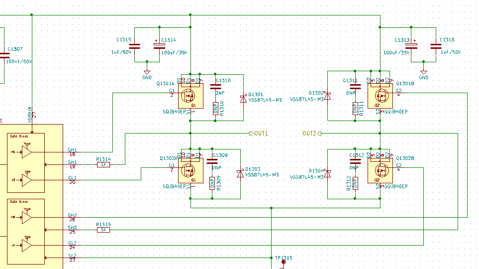
We had a situation where a DRV8703-Q1 was killed our application. We observed overvoltage spikes at the terminals SH1 and SH2, caused by the DC motor, connected to OUT1 and OUT2. We assumed that this was the reason for the malfunction and we added two simple 1k resistors in series to the inputs SH1 and SH2 (see R1314, R1315 in schematic below). Interestingly, the DRV8703 does not work with these resistors - using 10R resistors works well.  It seems that the current flowing into SH1 and SH2 is larger than expected (input current of these pins is not given by the datasheet).

Are there any hints how to dimension a series resistor for SH1 and SH2? Or are there any other ways how to protectthe inputs SH1 and SH2 against overvoltage?

Thank you,

Gerrit.

  • Hi Gerrit,

    The SHx pins on the DRV8703-Q1 are not intended to have resistors between the pin and the FET. Putting resistors here will interfere with our Smart Gate Drive and VDS overcurrent sensing features.

    I'm guessing that the spikes occur while the FETs are switching. If the FETs switch quickly, parasitic inductors and capacitors in the FET package and board routing will ring and cause spikes. I recommend using a lower IDRIVE setting. You can set this over SPI.

    If this does not help, please share your scope shot showing the voltage spikes.