This thread has been locked.

If you have a related question, please click the "Ask a related question" button in the top right corner. The newly created question will be automatically linked to this question.

TMS320F28335 motor conntroller using PS21A79 Intergrated IGBT, facing arm short circuit

Other Parts Discussed in Thread: CONTROLSUITE

Hi All

I currently developing a motor controller which using PS21A79 as main power components. But I facing issues on the IGBT controls. 

I Checked all the PWM signals connected to the PS21A79 was correct but when I slowly increase DC voltage on the PS21A79 then it shows high current draws by the IGBT when supply voltage over 7V. I had read again and again on the datasheet of the PS21A79, their one point that shows power ground and control ground can't be connected. This point I facing difficulty to understand. Anyone here in the forum using PS21A79 as driver? Any commons? My diagrams attached also. I didn't connect power ground and digital ground yet. 

  • 1. Please check all 6 PWM channels to see if there are deadtime between all 3 pairs PWMs, and the deadtime is enough as the power module requirement. Don't connect the motor first before the power inverter was verified.
    2. The control ground should be connected to the power ground together if you are implementing non-isolation and hot ground design.

    Please have a look at the HV-Kit design in controlSUITE that should be similar to your design.
    www.ti.com/.../controlsuite
    C:\ti\controlSUITE\development_kits\HVMotorCtrl+PfcKit_v2.1\~HVMotorCtrl+PFC-HWdevPkg\HVMotorCtrl+PFCKit-R1.1
  • Hi Yanming

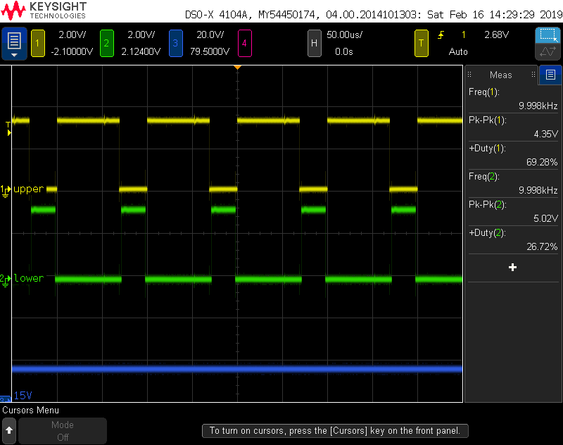
    Thanks for your reply. After seen your reply,  then I connected the power ground to control ground. and also checked on my PWM dead time, which all ok for the PS21A79 IGBT. Typically response time needed 6us.  Today I just supplied a small voltage to the IGBT , (5V, 0.4A). when switching start, power supply shows full current drawn from the IGBT. This should not have much current drawn since output terminal no connections. Below picture shows my observation, seems the IGBT could not follow the PWM signal input, I tried to replace new PS21A79, Issues remain. 

    U out is the IGBT output refer to GND.  Due to high current draw, so the circuit becomes consistent current.

    U upper is PWM signal 3.3v 5khz.


  • You have to check if the PCB layout design ow power supply to IPM have any problem on power module since the PWM outputs are right from the controller. You might refer to the datasheet of the IPM, or ask IPM manufacturer to check PCB layout.