This thread has been locked.

If you have a related question, please click the "Ask a related question" button in the top right corner. The newly created question will be automatically linked to this question.

DRV8806: Need SPI-controlled buck-regulator (12V - 24V with 0.5V step resolution)

Part Number: DRV8806
Other Parts Discussed in Thread: TPS92518, TPS54286, , TPS54283, TINA-TI

I need a SPI-controlled buck-regulator with an output ranging from 12V to 24V with 0.5V step resolution.  The input voltage is 28V and the max load is 1.5A.  I also need a second buck regulator with a fixed 7VDC output with a max load of 0.5A.   Will the DRV8806PWPR do the trick ?  If not, what solution would you recommend ?

  • Allen,

    Let me see if I can find someone to help you with this. It will be Monday though.
  • Instead of a low-side motor driver, perhaps a LED driver might be something to consider ?  For example, TPS92518.

  • Allen,

    We do not have dedicated 28 V (or higher) input dedicated buck converter with SPI interface. You may possibly get TPS92518 to work, but is is designed specifically to drive LEDs and the SPI interface controls the peak current rather than the output voltage. I would recommend looking at TPS54286 for both your fixed and variable outputs and use the SPI interface TPS0501 digital potentiometer as the low side feedback resistor of the variable output supply. Let me know if that will work for you.

    www.ti.com/.../tpl0501-100.pdf
    www.ti.com/.../TPS54286
  • Hi Allen,

    The DRV8806 is only a low-side driver, so it won't work as a buck. There are motor drive ICs in our portfolio with SPI, but I don't think they will accomplish your needs here. Hopefully John's suggestions work for you.

  • John,

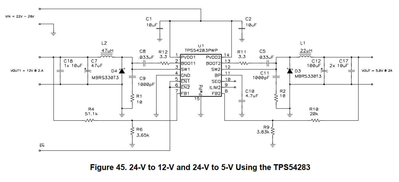
    I like your suggestion of using a TPS54286 combined with a  TPL0501-100DCNR.  Could you assist with component values ?  Perhaps we can start with Fig45 in the TPS54286 datasheet and adjust values so that :

    VOUT1= 12V -to- 28V in 0.5V steps (SPI-controlled). IOUT1 =1.5A,max.

    VOUT2 = 7V (fixed).  IOUT2 = 0.5A,max.

    Please let me know.

    Thanks,

    ~Allen

  • Allen,

    The TPS54283 datasheet has design procedures and examples. I would follow the design procedure for each of your outputs. I would start with the fixed output supply first, as it is easier. When you do the adjustable start with using the lowest output voltage as your design input as it should be the worst case, then double check it against the maximum value. There are pspice and TINA-TI average models you can down load from the tools and software tab to check your loop stability. I think you can use the same values in the above schematic for input capacitors, BOOT cap and resistor, RC snubbers fro SW to GND and BP cap. Your resistor dividers, output inductors and output capacitors will likely change. You can figure out the steps required for the digital pot and choose the upper resistor based on that.

    Let me know if you have questions, but I will have to leave it to you to actually design the circuit.