This thread has been locked.

If you have a related question, please click the "Ask a related question" button in the top right corner. The newly created question will be automatically linked to this question.

DRV8873: DRV8873S Current Sense

Part Number: DRV8873

Hello there,

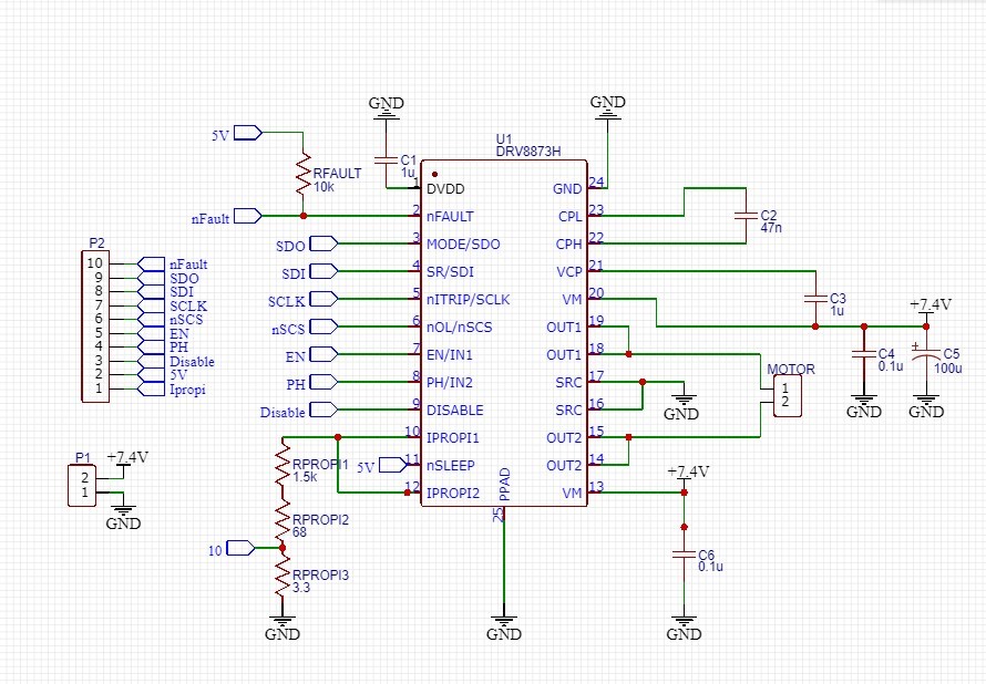
I have made a breakout board fot the DRV8873S in order to control a DC motor in PH/EN mode. I have coded a PD-position regulator for the project and now i need to read a current. According to the information in the datasheet i have calculated an appropriate Rsense: maximum current in 3.5Amps, so Rsense =  1100 * 5V / 3.5A = 1571 Ohm. The Vpropi is output from 10 pin on the picture. 

Here comes the problem. As a microcontroller i am using Atmega 328p (Arduino UNO), which has 10-bit ADC. But I am getting 82/98 out of 1023 from the ADC, even if i try hard to revolute motors shaft. I feel the great resistance on the shaft since i have a regulator, but the current, red by ADC doesn't change. Am i doing something wrong?

Best regards, Nikita

UPD:


I have made some tests: had connected multimeter in series with +7.4V to driver, when i applied presure on the motors shaft the current raised up to 1Amps. I tried to measure Vpropi, but it is less than 3mV with the same test conditions. What is wrong? 

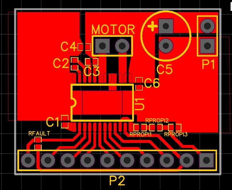
Here is my layout:

  • Hi Nikita,

    If we look at the resistor sets you have on IPROPI1 and IPROPI2, they do add up to ~1571 Ohms, yet you placed the node that leads to the connection to the ADC between resistance 1.5k + 0.068k and 0.033k. If IPROPI voltage reaches a maximum of ~5 V, you will have a maximum voltage at the 0.033k resistor of 0.103 V. (I calculated this value with a voltage divider equation). Taking that 0.103 V and multiplying it times the 1023 of your ADC, you get a max reading of 0.103 * 1023 = 105.37, which what your ADC is probably seeing. 

    As for your update, that IPROPI value is odd. Do you have the 5 V applied to nSLEEP to wake up the device? Do you have it disabled (the DISABLE pin)? Are you certain you are not utilizing a part that was damaged with the CPUV fault? If you changed the driver due to your previous issue, have you verified the soldering was done correctly and you have no open nets or shorts?

  • Helle, Hector,

    So, your are saying I won't even get 5V Vpropi, because of my layout? What do you mean, saying "If IPROPI voltage reaches a maximum of ~5 V"? 
    Your calculus is wrong a bit, because I have 3.3 Ohms Ipropi3 that is 0.0033k, so according to the voltage divider equation I will have voltage of 0.0033V, which is 33.759 on the ADC, not even close, unfortunately... 
    I am not very good at electronics, this is actually my first breakout board, so maybe I made a node to output pin in the wrong place of the resistor series? Can you help me improve it to make work properly?

    Talking about the values from multimeter. I have no faults in both registers, but sometimes i am having UVLO fault. This is not a problem a simple switch off-on helps. I think this is because I have my MC and the driver turning on simultaneously, but that is not a problem.
    I have applied 5V to nSLEEP and connected DISABLE pin to GND. No shorts have been detected, no problems with driver and motor operation too, except for having current sense not working...

    So, there are three main questions after this:
    1. Is my Rsense layout correct (may i have 1023 on ADC theoretically if the current is 3.5A)?
    2. Maybe there is something I should enable in order to activate Current Sense? Having almost nothing when probbing between Ipropi pin on breakout and GND is very strange. Or maybe I am probbing in a wrong place (might be)?
    3. Any diagnostics I can make in order to help us understand the problem?

    Thank you for your support!
    Thanks in advance!


  • Hi Nikita,

    Let's do a verification to find out on what node you do your ADC connection. On the image below this text, is it in the highlighted node?

  • Hi, Hector,

    Yes, i connect the ADC to the 10th node.
    I think I have understood the rules.. I have to change 1.5K and 3.3 Ohm resistors and better to move the 10 node to the place between 3.3 and 68, so i will have 3.3 and 68 + 1.5K. And the maximum voltage will be 4.998V, am i right?

    Thank you!

  • Correction to the image below this text.

    Something like this setup will do:

    I will brainstorm a bit more about your other issue.

  • Okay, you mean, that the resistor series should go after the node?

    And now i will try to solder 1.5K resistor to Rpropi3 position to get closer to the schematic you have drawn.

  • For further clarification:

    ADCs have a reference voltage for their operation. If you have your MCU configured to have an reference ADC value of 5V and its resolution count is 1023, then 5 V can be the voltage equivalent to ADC sample value 1023, which explains the example values I mentioned to you.

  • Hi Nikita,

    Is your motor spinning when you measure the IPROPIx voltage?

  • Oh, thank you for clarifying! 

    I have resoldered Rsense resistors. Now I have Rsense and the 10th node as you have drawn, but with 1.5K Ohm. Aaaand it is working! That totally made my day!) Having 1.5 Ohm resistor instead of a 1.571 is not a problem. The maximum possible measured current is now close to 3.7Amps. 
    Everything is good now and I can finally continue creating a prototype of a force-dynamic control system for a robot servodrive.

    Thank you very much!
    By the way, i am very pleased by TI support and will continue shopping here.

    All the best to you, Nikita