This thread has been locked.

If you have a related question, please click the "Ask a related question" button in the top right corner. The newly created question will be automatically linked to this question.

DRV8308: Boot up issue after chip Power-Cycle

Part Number: DRV8308
Other Parts Discussed in Thread: DRV8303,

Hello TI team,

I am facing one issue with our Motor-Driver boards that integrates DRV8303 chip. This board is integrated within an Energy Storage System. This design is in production for more than one year now.

Issue: After the DRV chip has been power cycle. It happens quite frequently that DRV8303 driver isn't responsive anymore on SPI bus after boot-up.

To provide some context, our board integrates a MCU and interfaced through SPI bus to the DRV chip. MCU and DRV chip are powered by two different power supplies: PSU_CTRL for MCU and PSU_PWR for DRV chip and for motor DC bus:

  • It turns that this issue occurs on some board but never on some other ones.
  • DRV chip ENABLE pin is always set active by MCU even during the whole power cycle.
  • DRV chip happens to not be responsive in a really repeatable context: The PSU_PWR OFF period shall be above a certain duration but not too long. If OFF period is long enough the DRV chip boot-up properly and is always responsive.

Consecutively to the fact that I was able to repeatably re-create the issue, I instrumented the board to capture PSU_CTRL, PSU_PWR (DRV8308_VM) and DRV8308_VINT (Internal DRV chip core power supply) in order to figure out if this timing behaviour could be the consequence of some internal power supply behavior upon power cycling.

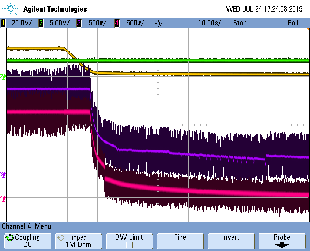
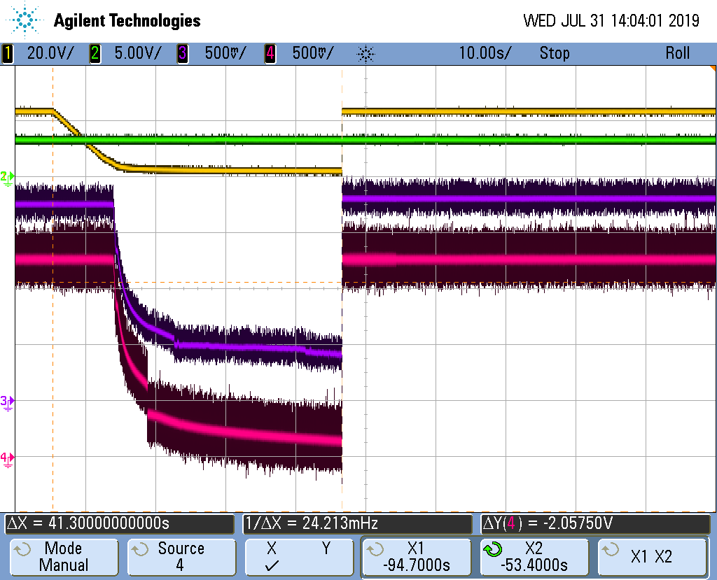
I obtained the following scope capture:

CH1 (Yellow): [Motor 2] PSU_PWR Voltage (DRV_VM)

CH2 (Green): [Motor 2] PSU_CTRL Voltage (3.3 V for MCU)

CH3 (Purple): [Motor 2] DRV8308_VINT Voltage


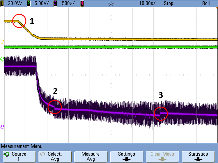
Step #1: PSU_PWR turned OFF

Step #2: First voltage discontinuity appears on DRV8308_VINT

Step #3: Second voltage discontinuity appears on DRV8308_VINT


Observation:

  • If I bring back PSU_PWR Voltage (DRV_VM) between Step #2 and Step #3, I will always have the DRV Chip bring-up issue.
  • However, If I bring-up PSU_PWR Voltage (DRV_VM) after Step #3, the chip will always boot-up properly and be responsive on SPI bus.


In the field, we don't have the possibility to adjust the power cycle OFF time duration. Therefore, we are unable to operate some systems in the field when this issue occurs.

Do you have any idea of what the rootcause can be and what can be a potential way to mitigate that? I would really appreciate any help with this problem.


Many thanks in advance.

  • Hello,

    I am asking my team about this and I will get back to you soon.

    Regards,

    -Adam

  • Hello Adam,

    Thank you for your feedback, below some additional test results I would like to bring to your attention.

    Our board is in fact equipped with to identical Motor-Driver function build around the DRV8308 chip. The board I used to perform my test has one particular motor-driver function that is failing at boot-up: Motor Function #2; and the other one that never presents this failure: Motor Function #1. Following previously published test results, I instrumented the other Motor-Driver function DRV8308_VINT Voltage on the same board that never happens to show the issue in order to look for a potential behavior difference. (See scope capture below)

    CH1 (Yellow): [Motor #2] PSU_PWR Voltage (DRV_VM)

    CH2 (Green): [Motor #2] PSU_CTRL Voltage (3.3 V for MCU)

    CH3 (Purple): [Motor #2] DRV8308_VINT Voltage

    CH4 (Pink): [Motor #1] DRV8308_VINT Voltage

    Observation:

    • [Motor #2] DRV8308_VINT Voltage shows the same repeatable behavior has before.
    • [Motor #1] DRV8308_VINT Voltage seems to be powered down much more quickly and nicely when supply voltage drop below a certain DRV chip internal threshold.

    It is as if [Motor #1] DRV chip always gracefully cut-off all its internal modules when  PSU_PWR  drops below a certain value, whereas, the [Motor #2] DRV chip that fails to boot up seems to have its internal modules not shutting downs at the same timing.
     
    Best regards,
    Guillaume
  • Guillaume,

    This would point to a layout or schematic difference between the two identical drivers on the board. Please compare the two and let me know what you find.

    Maybe one of the devices is shutting down quicker because it is farther from the bulk caps or has a smaller bulk cap?

    Regards,

    -Adam

  • Adam,

    I confirm that bulk capacitor layout + value are identical for both Motor_Funtion #1 and Motor_Funtion #2 of the same board. (VM, VINT and VCP pin)

    Moreover it happens on some other failing board that it is actually Motor_Function #1 that is affected instead Motor_Function #2 for the particular one I've tested. Also, some other boards doesn't present this issue at all. It thus doesn't seems to be function/layout dependent.

    Regards,

    Guillaume

  • Hello Adam,

    Do you possibly have any feedback about this DRV8308 chip boot-up issue? Is there any DRV8308 boot-up known problematic behavior and possibly integration strategies to mitigate it?

    Best Regards,

    Guillaume

  • Guillaume,

    I am still looking into this and will get back to you tomorrow.

    Regards,

    -Adam

  • Hello Adam,

    Understood, thank you for your support in attempting to understand the root cause of this issue.

    Best regards,

    Guillaume

  • Guillaume,

    In the case where the boot-up fails, do you see the VINT voltage at 1.8V as expected? 

    Regards,

    -Adam

  • Hello Adam

    Yes, I confirm VINT Voltage goes back to 1.8V after the chip has been cycled and had failed to boot-up. (See scope capture below) In our my case, the Enable signal is always active during DRV chip power cycle. (I noticed that when Enable signal is low level, VINT Voltage is around 1.35 V)

    CH1 (Yellow): [Motor 2] VM Voltage
    CH2 (Green): [Motor 2] [Motor 2] Enable signal
    CH3 (Purple): [Motor 2] V_INT
    CH4 (Pink): [Motor 1] V_INT

    Best regards,

    Guillaume

  • Guillaume,

    Could you try one experiment for us?

    Wait until VINT has dropped to at least 300mV before reapplying power and check if the SPI works.

    You can place a parallel resistor on VINT to discharge VINT quicker if needed.

    Regards,

    -Adam

  • Hi Adam,

    Sure, please find the related scope capture below:

    CH1 (Yellow): [Motor 2] VM Voltage
    CH2 (Green): [Motor 2] Enable signal
    CH3 (Purple): [Motor 2] V_INT
    CH4 (Pink): [Motor 1] V_INT

    Step #1: DRV_VM turned OFF

    Step #2: First voltage discontinuity appears on [Motor 2] DRV8308_VINT

    Step #3: Second voltage discontinuity appears on [Motor 2] DRV8308_VINT

    Step #4: Third voltage discontinuity appears on [Motor 2] DRV8308_VINT

    As you suggested, I switched VM back ON when VINT voltage dropped below 300 mV. (Monitored with a DMM) In this case DRV8303 is responsive on the SPI bus after boot-up.

    I noticed that this test doesn't lead to repeatable results as some time VINT voltage drops below 300 mV before step #4 and on next try it will drops below 300 mV after step #4. In this last case only, the DRV8303 (VINT purple CH3 trace) driver will be responsive on the SPI bus.

    Moreover, I leverage this post to add a better DRV chip behaviour description following some additional test I've performed on an actual DRV8308 chip that shows the boot-up failure. It seems that there is a kind of memory behaviour when the chip previous failed to boot-up properly (Non-responsive on SPI bus)

    Observation:

    • If PSU_PWR Voltage (DRV_VM) is brought back between Step #1 and Step #2, the DRV Chip doesn't show start-up issue only if it had previously started OK.
    • If PSU_PWR Voltage (DRV_VM) is brought back between Step #2 and Step #3, the DRV Chip doesn't show start-up issue only if it had previously started OK.
    • If PSU_PWR Voltage (DRV_VM) is brought back between Step #3 and Step #4, the DRV Chip will always shows start-up issue, even if it had previously been brought up OK.
    • However, if PSU_PWR Voltage (DRV_VM) is brought back after Step #4, the chip will always boot-up properly and be responsive on SPI bus whatever the chip was responsive or not on SPI bus before it has been power cycled.

    Hope this can help.

    Regards,

    Guillaume

  • Guillaume,

    What you are seeing is the digital core resetting itself and shutting down as the 1.8V regulator starts to decrease. In the cases that there is a startup failure, the Digicore is not getting reset correctly and therefore SPI will not respond on subsequent startups.

    It seems like your shutdown is taking a very long time, maybe almost a whole minute?

    Did you try the parallel resistor as I suggested?

    I would think that the answer here is to simply alter the VINT such that it shuts down much quicker and then the chip should always reset itself correctly.

    Regards,

    -Adam

  • Hello Adam

    Thanks for providing further detail about chip behavior upon power cycle.

    Indeed, the shutdown seems to take more than one minute in particular in the case when the motor are not running while the Motor-Drive function is power-cycled. This is likely due to a large amount of capacitance on the motor DC-bus.

    I haven't tried yet to integrate a resistor in parallel with VINT. What value do you recommend to start with and which load value to not exceed?

    Regards,

    Guillaume

  • Guillaume,

    You can start with a 10k and monitor the time it takes to discharge. We can adjust up or down from here.

    Regards,

    -Adam

  • Hello Adam,

    Understood, I will be able to perform some further testing beginning of next week. I'll keep you updated with the outcomes.

    Regards,

    Guillaume

  • Hello Adam,

    I had the opportunity to perform the test with integrated 10 kΩ resistor in // of the DRV VINT pin. I confirm DRV power cycle issue never occurs.

    V_INT pin then discharge 3x faster than previously (See scope capture below) preventing DRV chip power cycle issues for power cycle OFF duration from 0 to 40 s. This thus seems to be a great corrective update of our hardware!

    Also, as a possible containment action, I noticed that if ENABLE signal is set low during power cycle, the chip always boots up properly (Chip responsive on SPI bus). Does this behavior align with your knowledge of the chip behavior?

    CH1 (Yellow): [Motor 2] VM Voltage
    CH2 (Green): [Motor 2] Enable signal
    CH3 (Purple): [Motor 2] V_INT (10 kΩ resistor in //)
    CH4 (Pink): [Motor 1] V_INT (No 10 kΩ resistor in //)

    Finally, I am curious about what can cause the discrepancy we observe between the 2x DRV8303 of this same board, integrated into identical function and layout. Can this be explained by different DRV8303 chip version?

    Regards,

    Guillaume

  • Guillaume,

    Great to hear this fixed the issue. We haven't seen this issue before and we usually don't see VINT held up this high and for this long on other systems. 

    It makes sense to me that toggling ENABLE would help here as this would reset some internal nodes that help us additionally.

    I am not certain of the differences between your two devices but we also haven't reviewed the layout or schematic.

    Regards,

    -Adam

  • Hello Adam,

    Thank you for your feedback and your great help for this issue investigation. Part of our corrective update will be also to decrease our DC bus capacitance that in order to help VM dropping more quickly in addition of the parallel resistor on VINT.

    Again thank you for your help.

    Regards,

    Guillaume