


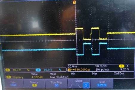
We're currently developing firmware for the TI DRV2510-Q1 driver in one of our medical imaging applications. We’re driving a couple square waves into the IN+/IN- pins of the driver. We’re seeing a lot of noise on the OUT+(yellow trace)/OUT-(blue trace) pins which could cause issues in our image quality:

Zooming in, we found the noise to be 400kHz, the driver PWM frequency:
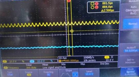
If I write 1 to register 0x03 bit0 I could change the frequency of the noise to 500kHz, confirming the noise source.
Here’s where things get interesting, I accidentally discovered that if I write 1 to bit 2(a reserved bit) of register 0x03, the noise goes away:
Although the datasheet didn’t specify a default value, I could read the default value on power up to be 0x78 for register 0x03. Bit 2 is zero by default.
In fact, I found that both reserved bits bit 1 and bit 2 has some effect on noise, writing a 1 to bit 2 appears to remove it. While doing this yields the desired behavior, I’m not comfortable driving a reserved bit. Please let me know if this is safe.
FYI, in these tests the driver is not connected to any load, standby pin is set to 0, en pin set to 1, register dump:
register 0x00 : 0x04
register 0x01 : 0x04,
register 0x02 : 0x84
register 0x03: 0xBE ( no noise with this value)
Thanks,
Tian

