This thread has been locked.

If you have a related question, please click the "Ask a related question" button in the top right corner. The newly created question will be automatically linked to this question.

DRV8343S-Q1EVM: Issues related to SPI communication with drv8343-q1

Part Number: DRV8343S-Q1EVM
Other Parts Discussed in Thread: DRV8323
Hi,
My question is related to DRV8343s while doing SPI communication for changing  6xPWM mode to  1xPWM mode. I am doing it with arduino mega.

Q1: Do    I need to connect all external capacitors which are related to VSDO and VP?
Q2: How can I check that mode (6xPWM mode to  1xPWMmode)  is changed after SPI communication? Can I check by supplying 1 PWM signal from arduino and check at gate outputs?
Q3: What changes need to be done in SPI related pins when SPI communication is done?
Q4: Do I need to connect all the mosfet before performing SPI communication?
  • Dilip,

    Thanks for posting on the MD forum!

    1. Yes all capacitors mentioned in the datasheet are needed.
    2. Yes this is a good idea.
    3. I don't follow your question, could you explain?
    4. Yes it is recommended to populate the board completely before operating the DRV and the SPI.

    Regards,

    -Adam

  • Thank Adam,

    I have written a code for SPI communication for changing 6xPWM mode to 1xPWM mode  for Arduino mega board.

    Can you please check the code? I am facing problem in reading the register.

    The code is

    #include <SPI.h>
    const int chipselect = 53;
    const int enable = 8;
    void setup() {
    Serial.begin(9600);
    pinMode(chipselect, OUTPUT);
    pinMode(enable, OUTPUT);
    digitalWrite(enable, LOW);
    digitalWrite(chipselect, LOW);
    SPI.begin();
    SPI.setBitOrder(MSBFIRST);
    SPI.setDataMode(SPI_MODE1);
    digitalWrite(enable, HIGH);
    delay(20);
    }
    void loop()
    {
    writereg(0x04,0xA7);  // adderess = 0000 0100, data = 1(fault) 000 0111 // last 111 for converting 6xPWM into 1xPWM mode
    readreg(0x84);        /// address= 1(read) 000 0100
    delay(1000);
    }

    void writereg(byte address, byte data)
    {
    byte HSend = 0x00,LSend = 0x00,HRead = 0x00,LRead = 0x00;
    HSend = address;
    LSend = data;
    Serial.print("Sending write command: ");
    Serial.print(HSend,HEX);Serial.print(" "); Serial.println(LSend,HEX);
    digitalWrite(chipselect, LOW);
    SPI.transfer(HSend);
    SPI.transfer(LSend);
    digitalWrite(chipselect, HIGH);
    Serial.print(HRead,HEX); Serial.print(" ");Serial.println(LRead,HEX);
    }

    unsigned int readreg(byte address ) {
    byte HSend = 0x00,LSend = 0x00,HRead = 0x00,LRead = 0x00;

    HSend = address;
    Serial.print("Sending read command: ");
    Serial.print(HSend,HEX);Serial.print(" ");Serial.println(LSend,HEX);
    digitalWrite(chipselect, LOW);
    SPI.transfer(HSend);
    SPI.transfer(LSend);
    digitalWrite(chipselect, HIGH);
    delay(20);
    digitalWrite(chipselect, LOW);
    HRead = SPI.transfer(0x00);
    LRead = SPI.transfer(0x00);
    digitalWrite(chipselect, HIGH);
    Serial.print(HRead,HEX); Serial.print(" ");Serial.println(LRead,HEX);
    }


    After running this code, I have received read data as 0xA0 in place of 0xA7.

    Thank you in advance.

  • Dilip,

    Unfortunately I am unable to check code snippets on the forum. Please use a scope or logic analyzer to read back the SDO communication due to your code and post the result here as an image.

    Regards,

    -Adam

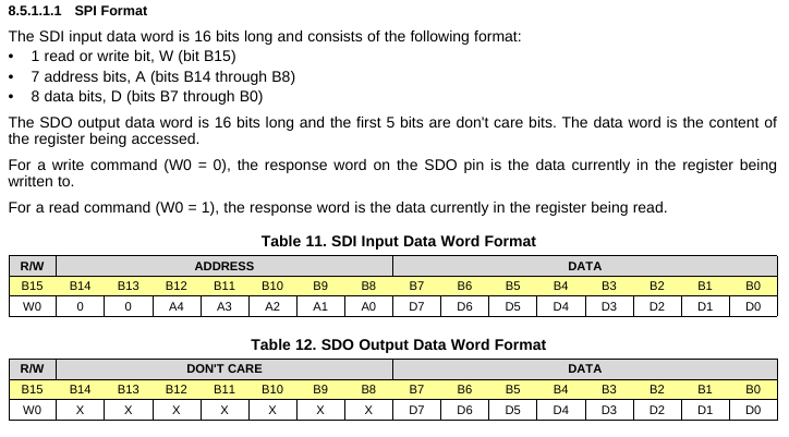
  • I have few questions related to the above image ( a part of datasheet of drv8343).

    Q1: The SDO output data word is 16 bits long and the first 5 bits are don't care bits, and SDO word shown in Table 12 has 7 don't care bits. Why?

    Q2:  For the statement "For a write command (W0 = 0), the response word on the SDO pin is the data currently in the register being
    written to.".  a. What is response word?  Is it the data already written into in the register, or is it directly bypassing the SDI data to SDO?

    b. If some bits sequence is available on SDO, does it mean that SPI communication is successful?

    Q3: what are the steps required in reading the register? As there are differences in SDO word format of different drv such as drv8323, particularly B15 (W0) which is not available in other drv.

  • Dilip,

    Q1) I am checking on this but I suspect this is a typo, usually the address in the SDO response is Don't Care so your 7 bits would be correct.

    Q2) I am checking on this.

    b) No, movement on the SDO line does not imply SPI is working completely, it may be working partially. For example there could be data integrity issues because a GND is missing or something.

    Q3) The steps are standard SPI and are mentioned in the datasheet here at section "8.5.1.1.1 SPI Format"

    Regards,

    -Adam

  • Dilip,

    I have confirmed that yes Q1 is a typo, is should be 7 don't care bits.

    Regards,

    -Adam

  • Thank you!

    What about W0 (MSB) on SDO data word format. Will it be available? This W0 is absent in other drv.

    Regards,

    Dilip.

  • Dilip,

    Could you explain what you mean by "available" as compared to other datasheets?

    Regards,

    -Adam

  • Dilip,

    I have seen no update on this thread, did your issue get resolved?

    I will mark this thread as closed for now but please post again if you need further assistance.

    Regards,

    -Adam