This thread has been locked.

If you have a related question, please click the "Ask a related question" button in the top right corner. The newly created question will be automatically linked to this question.

DRV10983EVM: Lock current limit problem

Part Number: DRV10983EVM

Hello,

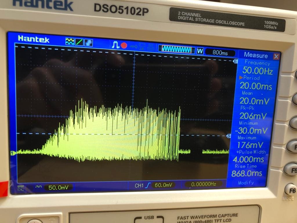
I am working with the DRV10983EVM and I am running my small brushless motor. It is starting and running smoothly both in open and closed loop. However, when I apply a sudden force on the rotating shaft it will stop running and lock with a current limit fault. On my oscilloscope I do not see any current spikes at the sudden impact. I apply the impact by just tapping on the rotating shaft, it does not take much force to stop it, just a sudden tap.The lock current limit is set to 3.2A, on my oscilloscope I read a maximum of 0.7A. 

Why does the system lock when I only apply such a low current?
I am not 100% certain whether the motor that I am using has a motor electrical constant of above 100us could this cause the problem? And if this causes the problem, which motor driver would you recommend with lower motor electrical constants?

The image below gives the voltage drop over a shunt resistor (0.3Ohm) to indicate the current. First you see the startup behaviour en next I tap the shaft which makes the motor stop with a Lock current limit warning.

Kind regards,

Robin

  • Hi Robin,

    I am not sure how you are measuring the stator current. Are you adding a 0.3 ohm resistor in series to one of the motor phases and measuring the voltage drop across it? If yes, then shouldn't we be seeing an unfiltered PWM square waveform?

    Can you measure and upload the actual stator current waveform while exerting the external force? Also, make sure the lock detection current threshold you set is less than the current the motor, the power supply and the device can handle.

    Regards,

    Vishnu. 

  • Hi Robin,

    Do you have any updates on this yet? Were you able to resolve the issue?

    Regards,

    Vishnu 

  • Hi Vishnu, 

    Thank you for your response. Not exactly. I am adding a 0.3 ohm resistor between the ground and the controller board such that the total current drawn is measured, including the current the controller draws, but this can be neglected. So we see a speed control PWM signal of 50kHz but zoomed out we only see the electrical motor speed frequency. So the uploaded figure is the stator current waveform. Can you make any sense of this?

    Kind regards,

    Robin

  • Robin,

    I'm not sure if that's gonna give an accurate stator current but my recommendation will be to use a current clamp and measure the stator current in the oscilloscope. 

    Regards,

    Vishnu

  • Dear Vishnu,

    I am sorry but we do not have a current clamp over here. However, the point is that we need to apply a variable load on the motor, and using this controller the current limit is reached far too quick. Furthermore, if all lock detects are disabled the motor starts making high tone noises under an applied load. The motor is theoretically strong enough do deliver a torque which I cannot stall with my bare fingers, however with this controller it is far too easy to stall the motor.

    I hope that you can answer the question without the stator current graph

    Kind regards,

    Robin

  • Robin,

    Sorry to hear that. Looks like there is a rotor alignment issue here which causes the motor to not able to generate the desired torque. Do you have the Initial Position detect (IPD) enabled? If yes, then can you play around with the IPD Advance angle to improve the efficiency? Also, do you have the software current limit setup in GUI? If yes, then can you set it up to whatever the motor's rated current is? Or even slightly higher?   

    Regards,

    Vishnu.

  • Dear Vishnu,

    The tuning guide says the following about the IPD:

    "IPD
    For applications where a reverse spin is not acceptable, the IPD function is an alternative way to initialize the motor. With the proper IPD setting, the motor startup is also faster.While this function is suitable for motors with high inertia,such as heavyblades (for example:a ceiling or appliance fan), it is not suitable for motors with low inertia, such as small blades (for example:a computerfan), because the current injection will cause the motor to shake, resulting in the IPD not being accurate. If IPD is chosen as initialization method,we need to enable IPD and configure the IPD setting section. At the same time,because the align method is not used, the Align Time can be set to the minimum value."

    We have a low inertia motor so I expect that my application is not suitable for IPD. I can get the motor working with IPD turned on but it does not change anything for my problem. It still switches off when I tap the shaft of the motor. I have tried both with and without the software current limit disabled but this doesn't change anything. The overcurrent lock will still trip at very low currents.

    If the software current limit is set to 1.4A and all the lock detect settings are switched off the motor will also stop very quickly (at 0.7A) but it will make high tone noises as I noted before.

    Regards,

    Robin

  • Robin,

    Can you share the screen-shoot of all the tabs in GUI? Did you measure the Stator resistance and the BEMF Constant of the motor? Do you have all the faults enabled? What is the fault/error code that you see in GUI when you tap the shaft of the motor?

    Regards,

    Vishnu

  • Dear Vishnu,

    I measured the stator resistance as well as the BEMF constant according to the following youtube video: https://www.youtube.com/watch?v=ix7YPvBtbvE

    When I have all the “lock detect” options enabled the error code that I see is the “Lock” with “Lock code 0” (overcurrent).

    The screenshots are given below

    Regards,

    Robin

  • Robin,

    Your image links are broken, can you re-upload them?

    Regards,

    Vishnu

  • Robin,

    Thanks for sharing the screenshots. From your screenshot it looks like the align time is too low. If increasing the align time doesn't help, I would recommend you to run the motor initially in open loop by following the steps from Section 4.1 to Section 4.8 in the tuning guide linked here.  Running the motor in open loop helps in choosing the right values in the startup settings. Once you have your motor running in open loop, you can follow the steps in Chapter 5 to run in closed loop. 

    Regards,

    Vishnu.

  • Robin,

    Do you have an update on this? Were you able to resolve the issue?

    Regards,

    Vishnu