This thread has been locked.

If you have a related question, please click the "Ask a related question" button in the top right corner. The newly created question will be automatically linked to this question.

DRV10983Q1EVM: speed command issue

Part Number: DRV10983Q1EVM
Other Parts Discussed in Thread: USB2ANY, DRV10983-Q1, DRV10987

Team, 

My customer is looking for help:

We have encountered a failure mode involving the DRV10983Q1EVM (evaluation board) and the DRV109XX EVM software and we wondered if any of your engineers could help us figure out the possible cause.

Currently, when a speed command is given over I2C to the evaluation board, the BLDC motor will immediately ramp up to max speed after crossing the Open loop to Closed loop threshold. Furthermore it will not respond to any subsequent speed commands given.

Through our debugging process, we have found out the following:

  1. The supply voltage VCC as read by the board is 11.8V when provided with 13V via power supply. 13V is read via multimeter on the VCC pin of the DRV10983Q1.
  2. The RPM calculated by the board is about 50% higher. For instance it reports 1800rpm for max speed when our motor is running at 1200rpm as confirmed via oscilloscope.
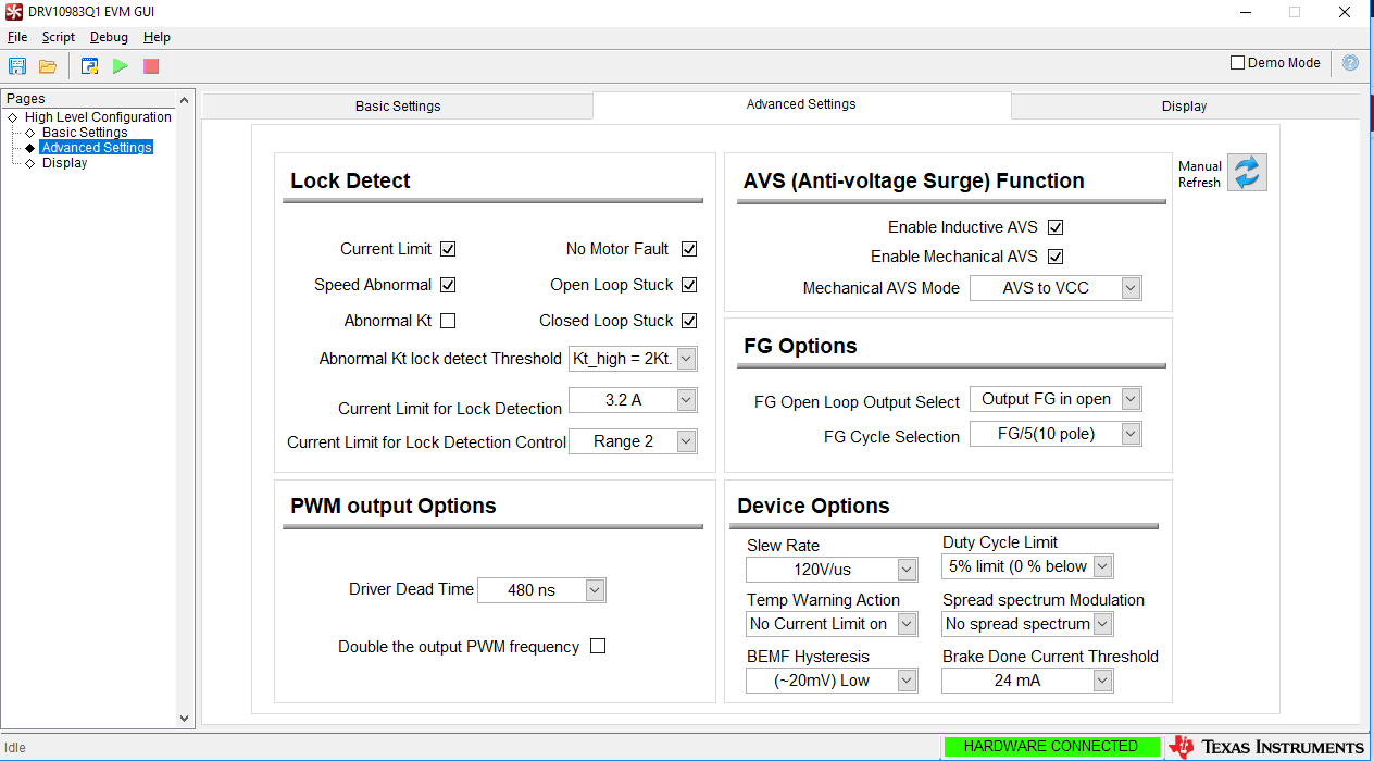
  3. If mechanical AVS is unchecked/disabled, then the board will respond normally to various I2C speed commands. However, the voltage and speed readings are still as seen in #1 and #2.

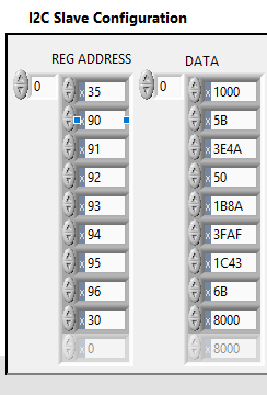
 Two different EVM boards have exhibited the same symptoms described above. For the previous 6 months, we had been manually setting the registers on the TI DRV109XX EVM software without encountering any issues. Then after making use of the configuration file, EEWRITE, and EEREFRESH features of the DRV109XX EVM software, we first noticed the abnormal behavior on both boards. The software version used was 3.2.2.0.

We have since updated to the latest software version of 3.3.4, but setting the registers manually does not fix the issue.

Are there any known issues that could cause this? If you need any additional information please let me know.

Thanks

Viktorija

  • Hey Viktorija,

    Thank you for the information. I'll split up this behavior into two separate issues:

    Currently, when a speed command is given over I2C to the evaluation board, the BLDC motor will immediately ramp up to max speed after crossing the Open loop to Closed loop threshold. Furthermore it will not respond to any subsequent speed commands given.

    This is a known issue that occurs when an unoptimal Kt is programmed into the device, and the Kt value is close enough to spin the motor but not close enough to the actual Kt. When this occurs, Mechanical AVS makes an incorrect judgement and tries to drive the motor or lock the speed command so the BEMF (where Kt = BEMF/f_electrical) is not larger than the V_applied or V_CC. Otherwise, current will flow from the motor (higher voltage potential) to the device or voltage supply (lower voltage potential), causing a surge.

    So now, we need to understand why the device incorrectly determined that the BEMF was large. Note our device does not measure the BEMF, and therefore, needs to obtain a value for the BEMF. The value for the BEMF comes from the ideal schematic of a motor model (which is shown below), where the phase inductance is ignored, U = voltage applied to motor phase, I = current that flow through motor phase, Rm = the programmed phase resistance, BEMF = Kt_programmed*f_electrical, and f_electrical = the commutation frequency or speed. If we apply Kirchoff's voltage law, we come up with the equation:

    U = I*Rm + Kt_programmed*f_electrical = I*Rm + BEMF

    As a result, the equation probably calculated the BEMF being large because the programmed Kt is too large. As a result, we can either:

    • Manually decrease Kt until the behavior disappears
    • Remeasure the Kt by using an oscilloscope and voltage probe by manually spinning the rotor and measuring the frequency and amplitude of the waveform
    • Use the device's estimated Kt by disabling closed loop or Mechanical AVS, looking at the BEMF Constant (Kt) box on the Display tab of the GUI while the motor is running, and inserting the new Kt value into the Motor Parameters box on the Basic Settings tab
    • Disable Mechanical AVS and increase the bulk capacitance on VCC to reduce the peak voltage when a surge occurs

    The RPM calculated by the board is about 50% higher. For instance it reports 1800rpm for max speed when our motor is running at 1200rpm as confirmed via oscilloscope.

    Thank you for providing the version number, the incorrect RPM calculation is a known issue in v.3.3.4 in particular. We should have a v.3.3.5 update relatively soon to fix this issue

    As an alternative, RPM = 120*f_electrical/n_poles should be used to calculate RPM. It sounds like you are already doing this, which is good.

    Best,

    -Cole

    Edit: Fixed picture

  • Thank you, Cole.
    It seems that image you have embedded is not available/doesn't load.
    Can you email it to me?
    Thanks
    Viktorija
  • Hi Cole,

    Follow up observations/questions:

    So far I am not positive that the issue is related to the parameters.  We used the following parameters listed below for 6 months with no issues and they work on our own internal development boards. The same parameters were tested on a new TI evaluation board with no issues seen when manually configured. I have also attached pictures of our settings within the GUI.

    DRV10983Q1 0x90 0x45B

    DRV10983Q1 0x91 0x3E4A

    DRV10983Q1 0x92 0x50

    DRV10983Q1 0x93 0x1B8A

    DRV10983Q1 0x94 0x3BAF

    DRV10983Q1 0x95 0x1C43

    DRV10983Q1 0x96 0x6B


    The TI GUI was used a few weeks ago to make use of the save and load a configuration file (.cfg) feature under the File tab. This was when the EEWRITE and EEREFRESH options were used and the abnormal behavior was first noted. The process was repeated on another DRV10983Q1EVM evaluation board with the same effects seen.

    I attempted a few of the proposed solutions. Note the tuning guide was originally followed to obtain the Rm and Kt values seen in the attached screenshots.

    1. By manually decreasing the Kt, the speed command will no longer lock at a value of 73.6mV/Hz. However, the voltage is still being read at 11.8V instead of 13V and the speed is not being calculated correctly as previously mentioned. The frequency as seen on an oscilloscope and measured by a tachometer is 95Hz while the speed register is reading a value of 150Hz.
    2. When looking at the device estimated Kt in the display tab of the GUI, the KT is estimated at 68mV/Hz at the original settings after reaching max speed. When disabling the closed loop and AVS settings with an open to closed loop threshold of 25.6Hz, the Kt value seen is 110mV/Hz.

     As a follow-up, I was originally wondering if it is possible that the EEPROM was affected adversely when loading the configuration file. The motor disable bit was not checked before loading the configuration file and using the EEWRITE and EEREFRESH commands. When examining the configuration files in Notepad, I only noticed two things out of the ordinary.

    1. The internal test key was listed as 3A6C on the configuration file generated in the older version of software while the latest version of the software lists this register as blank.
    2. Sometimes EEPROGRAMMING2 is listed as 0001 and other times it is blank. I know this is the ready status of the EEPROM for communication.

    I understand the failure mode is complex, does this issue sound reminiscent of anything you’ve encountered?

    Thanks

    Viktorija

  • Hey Viktorija,

    Config files and EEPROM

    Unfortunately, I haven't seen anything like this before. I agree that the problem seems more like EEPROM or how the GUI processes .cfg files. Whenever "Open Configuration" is used, the GUI will try to write all of the registers and settings. This includes settings such as Override or Motor Disable, that are not stored in EEPROM. I would guess that the .cfg loading process is causing some unexpected issues with the device, especially it implementing the register manually fixes the problem.

    Checking on bench, the eeWrite EEPROM process follows the correct procedure in the datasheet and the EEPROM Ready bit comes back as expected. As a result, I'm not yet convinced that the EEPROM process is corrupted.

    As a workaround, please try saving and loading the EEPROM settings using the buttons in the Motor Configuration section of the GUI and manually configuring (or running a script) for other registers, such as I2C override. If you don't know how to create and run a script, some helpful text should be in the appendix of the EVM User's Guide. I will try to recreate the issue on the bench but I agree that this failure is complex and I can't guarantee it will work.

    VCC Not Measured Correctly:

    The VCC is measured by a resistor divider network, internally to our part. The output is fed into ADC which then scales the value. While this contributes some error, we only expect less than couple of % error between the real and measured VCC value.

    As a result, does the error get better or worse if they choose a different value for VCC? In addition, if the we do not change the voltage supply but change the board (or just the device with the same board) is the VCC still scaled down to the same amount or the same percentage? We need to understand where the source of error could be coming from.

    The Measured Speed Isn't Correct:

    Let me provide information about each of the ways that our device can measure speed.

    FG is a pure analog block that translates the speed (electrical commutation) of the motor so it will be most accurate for calculating speed. With that said, the MotorPeriod register 0x02[15:0] is a 16 bit value that is sampled right off of the analog block used for FG and the MotorSpeed Register 0x01[15:0] is actually a 12 bit calculation of the inverse of MotorPeriod. This leads to some ~6% error between MotorPeriod and MotorSpeed.

    Just like VCC, the error is higher than what we expect. As a result, please have them measure FG (or the current of phase U) and compare it with the tachometer. Will using a different board, device, or tachometer yield different results? We need to eliminate possibilities of what could be causing the problem.

    Best,

    -Cole

  • Hello Cole,

    Viktorija had been posted on my behalf but she is out of the office today so I was given the link to this post to continue the conversation.

    Config files and EEPROM

    To clarify, setting the register manually does not fix the problem after it happens. Rather configuring the settings manually has been proven to work throughout development and works on other boards that have not had a configuration file written to them. The two evaluation boards that have had the configuration file loaded and written to the EEPROM both still exhibit the abnormal behavior despite attempts to reset the EEPROM.

    Is there a method to completely clear, liken to formatting, the EEPROM?

    Thanks for the advice about the Motor Configuration and script as an alternative method.

    VCC Not Measured Correctly:

    We have tested with two different power supplies and three different evaluation boards to confirm that the scaling is only happening to the two affected boards. The voltage scales with the power supply as seen below.

    VCC (Display Settings) Power Supply VCC
    9.17V 10V
    10V 11V
    10.9V 12V
    11.8V

    13

    From this it is seen that the VCC is always about 91% of the Power Supply VCC.

    The Measured Speed Isn't Correct:

    A waveform of the FG and phase current U has been attached as measured on an oscilloscope. The motor has ramped up to full speed which is measured as a typical value of 1100~1150RPM by tachometer. The oscilloscope has calculated a frequency of 94.4Hz for the FG pulses. Using the equation, (120*94.4) / (10 poles) = 1132.8 RPM. For some reason the frequency of the phase U current was varying in the kHz range, but from the waveform it is seen to match the FG pulses so that could be an equipment error.

    This contrasts with the results seen in the attached screenshot of the display settings which reads 156Hz.

    I also realized that we now get a BEMF abnormal fault that appears and persists once the motor reaches max speed. This happens with both AVS on and disabled. Previously the fault would sometimes appear but it could be cleared. After the failure happened, the fault now persists.

    Regards,

    Nathan

  • Also for comparison sake, I have included a screenshot of the display settings with the unaffected DRV10983Q1 evaluation board. The same exact parameters are used, meaning that AVS is on and the same Kt value is used. The motor spins as expected and responds to all I2C speed commands. Moreover, the voltage and motor speed in Hz is within the expected levels of error.

    Thank you for your time and I appreciate any insight,

    Nathan

  • Hey Nathan,

    Apologizes for the delay, I was vacation for the past few days. Here's my response:

    Config Files and EEPROM:

    Unfortunately, we write into the blank EEPROM when manufacturing the device and the only way to "re-format" the EEPROM would be writing zeros to all the appropiate registers. I would think this isn't what you're looking for.

    VCC Not Measured Correctly:

    Thank you for the data, let me talk with the team internally and see what the problem could be.

    The Measured Speed Isn't Correct:

    Good to see that frequencies of FG (and the general shape of the phase current) is very similar to the tachometer. That means the speed registers are at fault

    These problems are pointing to the digital block:

    Can you confirm that the FG and current waveform correspond to the Display tab on that you show in the same post? If so, can you confirm that the current and FG signals look the same during the "expected" behavior display tab screenshot that you see show in the follow up post?

    This shows that there is something wrong with how the numbers that we see on the GUI. This, to me, sounds like 3 possibilities for the errors:

    1. The digital block in the device is causing a large number of calculations to not work as expected
      1. This is a possibility but we haven't seen something like this occur before
      2. Also, I'd expect a power cycle to fix the problems and I'd expect our entire algorithm to fall a part unless a specific part of the digital block is damaged
        1. Do you have an example of a EVM working, then not working, then working as expected?
    2. The GUI is causing the problems
      1. I think this is the least likely, no other customers have reported something to the extreme we are seeing
      2. I'm not sure exactly how to test this without getting a hold of the test set up that is used
    3. There is some sort of problem with the communication between the GUI and the EVM (USB2ANY)
      1. I noticed that two different boards were used, did you try different USB2ANYs as well?

    Best,

    -Cole

    Edit: Can you also give me some of the settings that you use before you click the "save configuration" button? It would help make the EEPROM and Config file tests a bit closer to what you are doing.

  • Any Update?

    Best,
    -Cole
  • Hello Cole,


    Sorry for the late reply. My company moved office buildings, so my hands have been tied up for a few days. I am working on unpacking the testing equipment but I can provide an update in the meantime.


    These problems are pointing to the digital block:

    Can you confirm that the FG and current waveform correspond to the Display tab on that you show in the same post? If so, can you confirm that the current and FG signals look the same during the "expected" behavior display tab screenshot that you see show in the follow up post?

    Yes, the FG and current waveform do correspond to the Display tab within that post. The frequency of the FG pulses as measured on the oscilloscope is 94Hz while the GUI was showing 150Hz.

    I can work on getting an oscilloscope capture from the unaffected EVM board.


    1.     Do you have an example of an EVM working, then not working, then working as expected?

    No, once the EEPROM was written onto the EVM it would no longer work as expected. Any attempts to repair the board via resetting the EEPROM or power cycling the board has not worked.


    We have however, seen a potentially related issue with one of our designs using the DRV10983Q1. Using the debugging software, our SW engineer followed the EEPROM access instructions to write the register settings to the EEPROM as detailed in section 8.3.6 of the driver’s datasheet. He claimed that after following the instructions completely and detaching the debugging connector from the pins, the motor would stall during startup. This implies that the EEPROM was not programmed successfully. The register settings being written over I2C would function fine when the debugging cable was connected, and they are the same settings used in the GUI on the EVM boards. Next our SW engineer said that he stopped following the instructions after the mass write step and did not attempt the mass read. The motor would successfully run at half speed as programmed to do when powered on and given a switch command with the debugger disconnected.


    Does that sound familiar to any known issues or programming mistakes that can occur during this procedure?

     2.     I noticed that two different boards were used, did you try different USB2ANYs as well?

    Yes, two different USB2ANY’s were used with no observable difference.

    Below are the register settings used to run the motor and what was within the saved configuration files.


    Regards,

    Nathan


  • Hey Nathan,

    VCC scaling, Incorrect speed, and BEMF error (cont.)

    Apologizes for the delay. At the moment, we're still rather stumped by the behavior you're seeing. We've tried to recreate the same procedures on our bench with an EVM with the same settings you've sent and we cannot replicate the behavior here. Perhaps we can talk with Viktorija about getting one of the EVMs returned to us.

    One step we can try to run out the GUI is to install the GUI software onto another computer and see if the problem persists with the same board. If it does, we can narrow it down to the part (most likely). If not, then we are sitll left with the GUI or the communication between the GUI and device.

    Edit: Another suggestion is to measure GND and VCC at the pins (not just VCC) with an oscilloscope so we can see if there is some significant ground bouncing during operation.

    The programming steps:

    Let me see if I understand the process correctly:

    1. Power up device in accordance with EVM User's Guide
      1. This is with the EVM right?
    2. Populate shadow registers (0x90 - 0x96) with desired EEPROM settings
    3. Manually follow procedure 8.3.6 in datasheet to write to EEPROM
      1. How do you do that? Scripting tab of GUI? Some other device that uses I2C to write to manually to the DRV10983-Q1
    4. Detach USB2ANY or I2C device
    5. Cycle power and observe motor stalling on start up
      1. Didn't try to attach a USB2ANY or I2C device reread the 0x90 - 0x96?
    6. Then 1-4 was repeated but the mass read wasn't used when repeating step 3
    7. Obeserve motor not stalling on start up

    If the process is correct above, is it repeatable?

    I've only heard of problems reading and writing from the device when the device triggers a fault or lock (this is why we use the motor disable checkbox during programming steps), or when the GND layout is not good and switching noise from phases couples into I2C communication.

    Best,

    -Cole

  • Hey Nathan,

    Also, please look at VCC on the oscilloscope and probe at the pin with the tip and probe at the GND pin with the Ground Lead on the probe. We're interested in seeing if there is a noise profile.

    Best,

    -Cole

  • Good morning Cole,

    As we are continuing progress on our development with the TI DRV10983Q1, we have decided to ship one of the EVM boards exhibiting the failure. We hope to find out if the failure is hardware or software in origin. I will follow-up with Viktorija regarding the shipping details.

    In the mean time, I discussed the EEPROM programming procedure with our SW engineer.

    Programming Process:

    1. Power up device in accordance with EVM User's Guide   -Our development board is being used
      1. This is with the EVM right?

    2. Populate shadow registers (0x90 - 0x96) with desired EEPROM settings   -Correct
    3. Manually follow procedure 8.3.6 in datasheet to write to EEPROM -A microcontroller on our board with I2C and programming software
      1. How do you do that? Scripting tab of GUI? Some other device that uses I2C to write to manually to the DRV10983-Q1
    4. Detach USB2ANY or I2C device
    5. Cycle power and observe motor stalling on start up   -Correct, there is difficulty in reading the I2C.
      1. Didn't try to attach a USB2ANY or I2C device reread the 0x90 - 0x96?
    6. Then 1-4 was repeated but the mass read wasn't used when repeating step 3 -Correct
    7. Observe motor not stalling on start up  -Correct

    To clarify, whenever we try to run the motor with the EEPROM it will stall on start up. I found out the SW engineer added a final step to use the shadow registers for operation and that is why the motor works without stalling after omitting the mass read steps. Moreover, instead of waiting for the status of the EEPROM to come back as ready, a 10ms delay was added to the code. This means that the EEPROM on our development board is functional but I believe the procedure needs to be followed more accurately. The stall is likely from an improper KT value in the EEPROM that doesn't match what we use in the shadow registers.

    Therefore, this is a different issue then what is seen on the EVM boards. The EVM board uses the shadow registers for the I2C speed command and yet it does not respond to different speed commands except for stop and then ramping up the full speed regardless of input; despite an identical configuration to the functioning EVM board. Even though the same error has not occurred on our own boards, we would like to understand the issue.

    Thanks,

    Nathan

  • Hey Nathan,

    The EVM should arrive on my desk very soon.

    As for the programming, we ran into a similar problem on the DRV10987. The DRV10987 is a similar device but the EEPROM architecture may be different so the solution might not be exactly the same. Essentially, we learned that the user had to wait 50ms after the EEPROM status goes high when going through the programming steps.

    If adding 10ms delay fixed the problem then it sounds like we can expect a similar situation for the DRV10983-Q1. I will confirm with our internal team if the EEPROM structure is the same and I should be able to give you a comment about the delay time.

    Thanks,

    -Cole

  • Hey Nathan,

    I've confirmed internally that the DRV10983-Q1 and DRV10987 have the same EEPROM architecture. As a result, please wait at least 50ms after the EEPROM status goes high.

    This has been added to the prospective datasheet changes for the DRV10983-Q1. Let me know this change does not fix the problem and thanks for you patience.

    I intend to work on the board I received from you tomorrow.

    Best,
    -Cole
  • Cole,

    Thanks for confirming that about the delay. I will make a note of that and relay it to our SW engineer so he can repeat the aforementioned programming process.

    I look forward to hearing about any clues regarding the EVM board.

    Thanks,
    Nathan
  • Hey Nathan,

    Since the part is returned, about to go through failure analysis, and we've been having some back and forth with Viktorija. I will close this thread and continue offline.

    Best,
    -Cole