This thread has been locked.

If you have a related question, please click the "Ask a related question" button in the top right corner. The newly created question will be automatically linked to this question.

DRV8323: AMC1301

Part Number: DRV8323
Other Parts Discussed in Thread: DRV8320, AMC1301, LM317HV, , DCH010505D

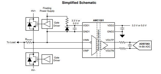
I design a 48V inverter with DRV8320. I would like to measure the phase currents with shunt resistor. I also like to isolate the current signal so I decided to use AMC1301 isolation amplifier. Based on the datasheet the VDD1 voltage should be generated by a zener diode from the floating power supply of the gate driver:


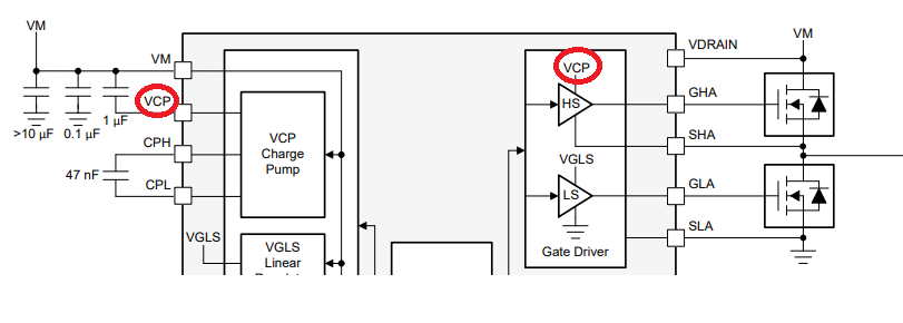
My question is, in the case of the DRV8320 can is use the VCP terminal (output of the charge pump circuitry) to generate the voltage using Zener diode for AMC1301?

Thank you in advanced

  • Hi stpepe,

    It may be possible to use the VCP, but the current required will reduce the ability to drive the high side FETs quickly.

    I have contacted the AMC1301 experts for their comments. I believe a LDO can also be used.
  • Thanks Rick -

    Welcome to the e2e forum stpepe! Yes, you can use an LDO for the VDD1 source as Rick suggested. I don't know what your VM is, but VDD1 has to be in the range of 3.3 to 5.5V.

  • Dear Rick and Tom!
    Thank you very much for your help.
    My problem is I do not exactly see how to connect the LDO to supply AMC1301 in my arrangement. I have a 48V DC inputvoltage to the inverter. The 3.3-5.5V VDD1 voltage is referred to the GND1 terminal, which is connected to the VINN, one end of the shunt resistor and the Source leg of the upper transistor. This point is floating. How can I supply the VDD1 with a 3-pin LDO (like LM317HV)? I can use an isolated DC/DC, but I looking for a simple solution. 
    Regards,
    stpepe

  • Hi stpepe,

    OK - I understand. Ideally you would be able to tap off the VCP, which is essentially the 'floating power supply' for the gate driver shown in your original post. The AMC1301 will use ~6mA of current on VDD1. If the DRV8320 can't source that current and still drive your transistors, you could use an isolated DC/DC.
  • Hi stpepe,

    Sorry for the delayed response.

    The DRV8323 charge pump can provide up to 25mA average current. So it is possible to use the charge pump as long as the FET switching consumes less than 19mA. Equations 9 and 10 estimate the amount of current required based on switching frequency.

    There is something that I think is more problematic. You have the GND1 side of the AMC1601 connected to the drain/source connection of the lower/upper FET combination. When the lower FET is enabled, the voltage across the resistor/zener combination will be VCP minus HV-. If HV- is GND, that would be ~60V.

    An alternative connection would be to connect GND1 to the HV+. This would limit the voltage differential to ~12V.
  • Hi stpepe,

    In addition to the prior message, please add a diode (anode to VCP, cathode to the resistor). This will prevent the AMC1301 capacitor holding VCP above VM when the charge pump is disabled.

  • Dear Rick!

    Thank you for your detailed answer. I will try first with using a small DC/DC, like DCH010505D, but perhaps I will test the arrangement, what you suggested as well.

    Regards,

    stpepe