This thread has been locked.

If you have a related question, please click the "Ask a related question" button in the top right corner. The newly created question will be automatically linked to this question.

DRV2605: Cannot get haptic feedback either with LRA or Piezo

Part Number: DRV2605
Other Parts Discussed in Thread: DRV2700,

Hello,

I am trying to get a haptic feedback either using LRA motor with DRV2605, or using piezo with DRV2605/DRV2700 (based on application report SLOA255).

When using just LRA, the haptic feedback is barely noticeable. However, when the LRA is driven directly from a power supply, the feedback is strong.
When using the DRV2700 with a signal from DRV2605, there is no feedback can be felt. I also notice that the FB pin does not output 1.3V. Thus my PVDD signal is around 10V instead of 65V.

Attached is the schematics of the haptic driver circuit. The selection between Piezo or LRA is done using J1 and J2 jumpers.

LRA motor - 1020-15-003-001 (www.digikey.ca/.../j2rmtd)
Piezo - Z63000Z2910Z 1Z 2 (www.digikey.ca/.../j2rm8v)

I am looking for any possible recommendation.

Thank you.

Regards,
Leon

  • Hi Leonid,

    Welcome to E2E, thanks for your interest in our devices.
    My colleague is out of the office, so He will be responding tomorrow with further information.

    Best Regards
    José Luis Figueroa
    Audio Applications Engineer
  • Hi Leon,

    I'll give a close review to the schematic but I have a couple comments at this moment:
    - Low-Pass Filter is not populated on the schematic (R37, R39, C8 and C9). Have you tried to place these components to form the LPF? The output signal from DRV2605 is a Class-D, so the filter is needed for the analog inputs of DRV2700.
    - You mention LRA motor for the DRV2605 actuators, but from the device description in its data sheet and digikey, as well as your comment about driving it with DC voltage, it looks more like a motor (like ERM). Are you configuring DRV2605 to drive an LRA or ERM actuator? If you're trying with LRA config, I would suggest to change it to ERM.

    Best regards,
    -Ivan Salazar
    Applications Engineer - Low power Audio & Actuators
  • Hello Ivan,

    Thank you for your prompt reply.

    For some reason, I thought that the motor is LRA type. I will update the registers and will test it as ERM motor.

    Regarding DRV2700 I have a few questions:

    1. I can definitely populate the LPF. What would be recommended cutoff frequency?
    2. While LPF might help to propagate the signal properly, I still have very low voltage on FB (around 0.3V). Thus, my PVDD is around 10V. I assume LPF does not control the internal boost converter. Why voltage on FB pin so low?

    Regards,

    Leon

  • Leon,

    Please let us know the results after changing device config for ERM.

    Regarding the schematic I found the following:
    Rext is 4-kohm? The minimum recommended from the data sheet spec is 6-kohm, the current limit for the boost might be out of spec. In addition, the current limit of the boost should be less than the rated saturation of the inductor L2. Using 4-kohm as Rext would set a current limit of around 3.5-A (theoretically as this is out of spec).

    Best regards,
    -Ivan Salazar
    Applications Engineer - Low power Audio & Actuators
  • Hello Ivan,

    I wanted to update you regarding the motor test. After changing the registers to drive the ERM motor, the performance of the motor immediately improved. We will continue playing with registers to get the best results.

    I understand your point regarding REXT on the DRV2700 circuit. I will replace the resistor and will update you on the results.

    Thank you again for continuing support.

    Regards
    Leon

  • Hi Leon,

    Please let us know the results of changing Rext; hopefully this will solve the situation with DRV2700.

    Best regards,
    -Ivan Salazar
    Applications Engineer - Low Power Audio & Actuators
  • Hello Ivan,

    Sorry for the delay in responding.

    As mentioned in the above post DRV2605 works properly for us.

    However, the DRV2700 still does not perform. I replaced REXT resistor to 10k. Unfortunately, it did not improve the performance. As soon as the EN pin is asserted high, the supply voltage drops from 5V to around 3.5V - 4V (board-dependent). Any suggestions? Troubleshooting steps?

    Thank you.

    Regards,
    Leon

  • Hi Leon,

    Thanks for the update. Is there a chance that you could share the voltage rating of the capacitors from your schematic? I'd like to make sure that the caps are rated for the correct voltage, I'm specially interested on the ones related to the boost.

    Best regards,
    -Ivan Salazar
    Applications Engineer - Low Power Audio & Actuators
  • Hi Ivan,

    All capacitors that are used for DRV2700 are 100nF, X7R, 20%, 50V (CGA2B3X7R1H104M050BD). I realize that C13 is below expected 68V boost voltage, but speaking with cap manufacturers, at 23 deg C, the capacitors can take significantly higher voltage than rated.

    Anyway, if you believe that this might be an issue, please let me know and I will try to find a capacitor with a higher voltage rating.

    Regards,
    Leon

  • Leon,

    For troubleshooting you could try a couple things:
    - Higher voltage rated cap on PVDD/BST
    - Disconnect DRV2700 input from previous stage (DRV2605)
    - Power DRV2700 with its own supply, eg. power up only DRV2700 and do not supply other devices in the system with the same source
    - In case of powering DRV2700 with batteries, change for DC Voltage Supply to check if current could be an issue

    Best regards,
    -Ivan Salazar
    Applications Engineer - Low Power Audio & Actuators
  • Ivan,

    I replaced the C13 cap to 08051C104K4T2A (100V, X7R, 10% 0805). The only issue is that it is 0805, so I had to do some adjustment was required on the board. However, the connections are solid.
    The input DRV2605 stage is disconnected by removing jumpers on J1 and J2. All other devices (except the microcontroller) are disabled by using their respective EN pins.

    After powering the circuit the results did not change. The same results are observed.

    Unfortunately, it would be extremely hard to power the DRV2700 from a separate power supply. It would require trace cutting, component lifting, and wire-up steps. I am not sure if that would be a good test.

    Regards,
    Leon

  • Leon,

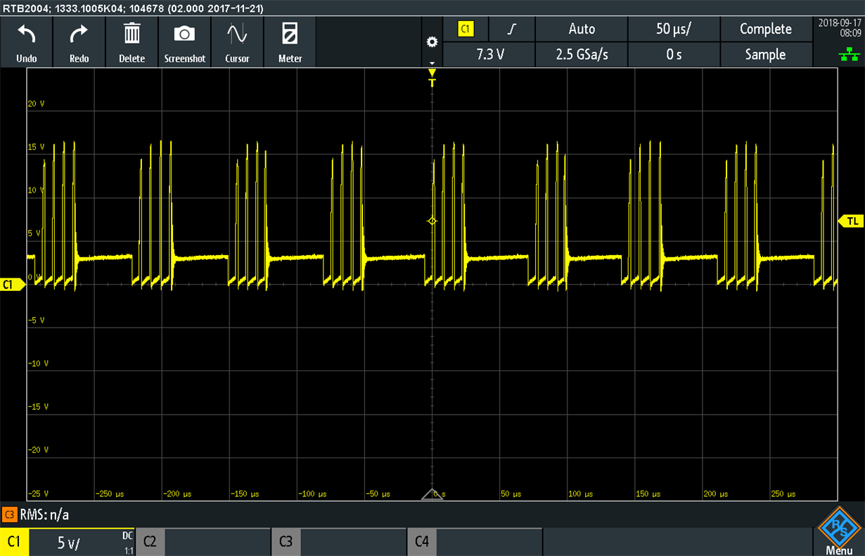
    Is there a chance that you could capture the signal at SW pin? I would like to know if this pin is switching or not.
    How is your whole system powered? By batteries or by external DC power supply? Can you power up the whole system (other ICs, uC and DRV2700) with a DC power supply? I just would like to know if current capacity is being an issue here.
    Trying different units of DRV2700 is possible? This could help to identify if the device could have got damaged.

    Last, one additional thing I would like to ask: When you test DRV2605 and it operates fine, is DRV2700 enabled or disabled? I would like to know if enabling DRV2700 could affect other devices in the system due to high current drain.

    Best regards,
    -Ivan Salazar
    Applications Engineer - Low Power Audio & Actuators
  • Hi Ivan,

    Attached is the screenshot of SW pin during operation. Please note at this stage the DRV2700 is only powered and enabled. No piezo connected and no input provided.

    The circuit is powered DC power supply and its limit is maxed (3A).

    I did try a few other boards before I contact forum. Unfortunately, I see sort of the same issues.

    When DRV2700 is powered and enabled, it is significantly affecting the supply rail (in some boards the supply drops to 4V and other to 3V). Please see the attached power circuit as well.

    Regards,
    Leon

  • Hi Leon,

    I apologize for the late reply.
    It seems like the device is having a hard time trying to start it operation. It would be good to know if SW pins are switching, this would let us know if the boost converter is operating.
    Have you tried with different inductors on L2? It seems like the inductor and the down converter are correctly spec in terms of current but just want to know if changing the inductor could affect the behavior.
    Current from power circuit should not be an issue as DRV2700 is even able to be supplied by USB 5V which is around 500mA max.

    Best regards,
    -Ivan Salazar
    Applications Engineer - Low Power Audio & Actuators
  • Hi Leon,

    I wanted to ask one more thing. Can you please capture the output of the 5V regulator without DRV2700 in the system? Or when it is disabled?
    And also when the device is present and enabled? (I'd like to see the transition between device disabled and then enabled) This would show if VDD is directly affected by the SW switching.

    Best regards,
    -Ivan Salazar
    Applications Engineer - Low Power Audio & Actuators
  • Hi Leon,

    We haven't heard back from you. We are assuming that you were able to solve your problem. If no, just respond to Ivan's questions.

    Best Regards
    José Luis Figueroa
    Audio Applications Engineer
  • Hello Ivan,

    I really apologize for long reply time. I was urgently dragged to a different project and I had to leave this project completely. I changed the 10uH inductor (IHLP2020BZER100M01) to 15uH inductor (IHLP2020CZER150M01). There is no change in performance.

    Any recommendations?

    Regards,

    Leon

  • Hi Leon,

    It has been some considerable time since last communication. Could you please start a new thread including the latest application status?
    This way we can remove DRV2605 from the thread since this one is working fine and also provide a better follow-up. Once you start the new thread we can close this one.
    Thanks in advance.

    Best regards,
    -Ivan Salazar
    Applications Engineer - Low Power Audio & Actuators
  • Hi Ivan,

    Thank you for your help. I will do that.

    Regards,

    Leon