This thread has been locked.

If you have a related question, please click the "Ask a related question" button in the top right corner. The newly created question will be automatically linked to this question.

DRV8320: DRV8320H Motor Hums but does not spin.

Part Number: DRV8320

Hi,

I'm having problems with DRV8320H.   Motor hums but does not spin. 

I am running with following settings..

* Supply Voltage 12.5V@24A.

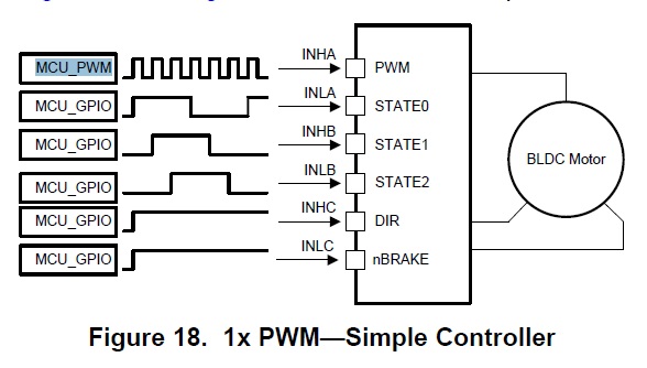
* 1x PWM with MODE pin floating.

* PWM /  I/O controlling from Arduino.

* IDRIVE and VDS are pulled up to DVDD with 18K resistor.

* Motor resistance between each phase is 0.3 Ohm.

* Motor configured as Delta Winding. 

Thanks,

  • Hello Raj,

    Couple of questions:

    1. Is a fault being generated?

    2. Is this your own board or TI EVM?

    3. Do you have a load? Please, spin motor without load first.

    4. Does VM = VDRAIN = 12.5 V?

    5. Have you verified the schematic and the connections to each FET are valid? No open nodes GHx, GLx, SHx.

    6. Have you verified connections from FETs to motor are valid?
  • Hector,

    1. Is a fault being generated?

    No...

    2. Is this your own board or TI EVM?

    My own board. 

    3. Do you have a load? Please, spin motor without load first.

    No Load at all.

    4. Does VM = VDRAIN = 12.5 V?

    When running it's 12.20V.

    5. Have you verified the schematic and the connections to each FET are valid? No open nodes GHx, GLx, SHx.

    Yes, everything checked.

    6. Have you verified connections from FETs to motor are valid?

    Yes....

    What is the drive time in between each states in 1x PWM mode? 

    I am using 4000ns drive time and 100ns dead time.

    FYI: 

    * Motor is working with delta and star configuration with other non-Ti Ebay controllers .

    * SLA, SLB, and SLC are connected to ground.

    * Mosfet specs...

    Logic Level Gate Drive (+/-20v max)•  75A, 30V •  On-Resistance, rDS(ON) = 0.0075Ω

    Turn-On Time tON 120 ns

    Turn-On Delay Time td(ON) - 16 - ns

    Rise Time tr - 65 - ns

    Turn-Off Delay Time td(OFF) - 90 - ns

    Fall Time tf - 55 - ns

    Turn-Off Time tOFF - - 218 ns

    Thanks...

  • Hi Raj,

    Are you using hall sensors?

  • Hector,

    No hall sensors...


    Thanks...
  • Hi Raj,

    Can you verify if your commutation is correct, according to Table 4 of the datasheet?

    Also, what PWM frequency are you using to commutate?

    I think there might be a commutation step being skipped.
  • Hector,


    Please see attached simple Arduino codes for commutation.
    The Align function works and it rotates shaft of the motor some degrees.
    /*
    ///////////////////////////////////////////////////////////////////////////////////////
    Pin 8 = Enable
    Pin 9 = PWM INHA
    Pin 10 = INLA STATE
    Pin 11 = INHB STATE
    Pin 12 = INLB STATE
    Pin 13 = INHC DIR

    INLC nBRAKE = tied to DVDD

    STATE INLA INHB INLB
    Stop = 0 0 0
    ALIGN= 1 1 1
    1= 1 1 0
    2= 1 0 0
    3= 1 0 1
    4= 0 0 1
    5= 0 1 1
    6= 0 1 0
    */
    //////////////////////////////////////////////////////////////////////////////////

    int enable=8;
    int PWM=9;
    int INLA=10;
    int INHB=11;
    int INLB=12;
    int DIR=13;

    int delai=5;
    int SPEED=50;

    void setup() {
    //PWM Frequency 3921 Hz
    TCCR1B = TCCR1B & B11111000 | B00000010; //3921hz
    pinMode(enable,OUTPUT); // pin 8
    pinMode(PWM,OUTPUT); //pin 9
    pinMode(INLA,OUTPUT); //pin 10
    pinMode(INHB,OUTPUT); //pin 11
    pinMode(INLB,OUTPUT); //pin 12
    pinMode(DIR,OUTPUT); //pin 13

    digitalWrite(enable,HIGH);
    delayMicroseconds(1);

    analogWrite(9, SPEED);
    delayMicroseconds(1);

    digitalWrite(DIR,LOW);
    delayMicroseconds(1);

    //STOP
    digitalWrite(INLA,LOW);
    digitalWrite(INHB,LOW);
    digitalWrite(INLB,LOW);
    delay(delai);

    //ALIGN
    digitalWrite(INLA,HIGH);
    digitalWrite(INHB,HIGH);
    digitalWrite(INLB,HIGH);
    delay(5000);
    }

    void loop() {
    //Direction = 0
    //STATE 1 B>C
    digitalWrite(INLA,HIGH);
    digitalWrite(INHB,HIGH);
    digitalWrite(INLB,LOW);
    delayMicroseconds(delai);

    //STATE 2 A>C
    digitalWrite(INLA,HIGH);
    digitalWrite(INHB,LOW);
    digitalWrite(INLB,LOW);
    delayMicroseconds(delai);

    //STATE 3 A>B
    digitalWrite(INLA,HIGH);
    digitalWrite(INHB,LOW);
    digitalWrite(INLB,HIGH);
    delayMicroseconds(delai);

    //STATE 4 C>B
    digitalWrite(INLA,LOW);
    digitalWrite(INHB,LOW);
    digitalWrite(INLB,HIGH);
    delayMicroseconds(delai);

    //STATE 5 C>A
    digitalWrite(INLA,LOW);
    digitalWrite(INHB,HIGH);
    digitalWrite(INLB,HIGH);
    delayMicroseconds(delai);


    //STATE 6 B>A
    digitalWrite(INLA,LOW);
    digitalWrite(INHB,HIGH);
    digitalWrite(INLB,LOW);
    delayMicroseconds(delai);
    }


    Thanks...
  • Hi Raj,

    1. Have you measured DVDD to make sure it is 3.3V?

    2. Your delai and SPEED parameters are how much regarding time?

    3. Your PWM is 3.921 kHz, correct?

  • Hector,

    1. Have you measured DVDD to make sure it is 3.3V?

    Yes....it's 3.196v


    2. Your delai and SPEED parameters are how much regarding time?

    Microseconds...


    3. Your PWM is 3.921 kHz, correct?

    Yes...

    I could not find the Launchpad codes for the evaluation board.... Is it possible to get to see how it drives?    Then I can implement on my own board with Arduino...    

    I need to know exact timing I need to apply in between the commutation states.

    Thanks...

  • Hi Raj,

    The thought I have relates to your commutation speed. It appears you communicate without getting positional feedback from halls, voltage zero crossing, or current measurement on the feedback. If the only parameter that separates you from proceeding to the next commutation is a delay, it might be too fast or too slow and the motor magnets do not have enough time to energize and commutation the phase change or take a long time between each phase change.

    Launchpad code can be found here:

    www.ti.com/.../slvc683

    Install the firmware executable, and during installation you can see in what directory location the firmware installs in so you can view the source code.
  • Hector,

    Does  eval board codes support parallel control?   I am trying to achieve with figure18 synchronous 1x PWM mode.

    Thanks...

  • Hector,

    I am able to spin motor at low speed 20ms delay in between the states @25 PWM (0-255)

    Thanks...
  • Hector,

    I am able to spin motor at low speed, 20ms delay in between states.

    Thanks...
  • Hi Raj,

    This e2e slipped. Have you resolved the issue of spinning the motor at your desired speed?

    What do you mean by parallel control, exactly? Thank you.
  • No luck, I am behind on the schedule. The DRV8320 specs does not show exact timing i need to apply to drive in 1X PWM mode or i may have overlooked.
  • No luck, I am behind on the schedule. The DRV8320 specs does not show exact timing i need to apply to drive in 1X PWM mode or i may have overlooked.
  • What is your exact timing?
  • Hi Raj,

    If I can be of anymore assistance, let me know.
  • Hi Raj,

    I am closing this thread. If you would like any further assistance, please start a new thread or reply back in this one. Thanks.

  • Problem still exists and cannot be solved from my side...
    Do not close this thread..
    Thanks
  • Hi Raj,

    When you say the timing you need, do you mean the PWM is 3.921 kHz? Or is it any other timing parameter