This thread has been locked.

If you have a related question, please click the "Ask a related question" button in the top right corner. The newly created question will be automatically linked to this question.

DRV10983: PROBLEMS IN OPEN LOOP AND CLOSE LOOP

Part Number: DRV10983

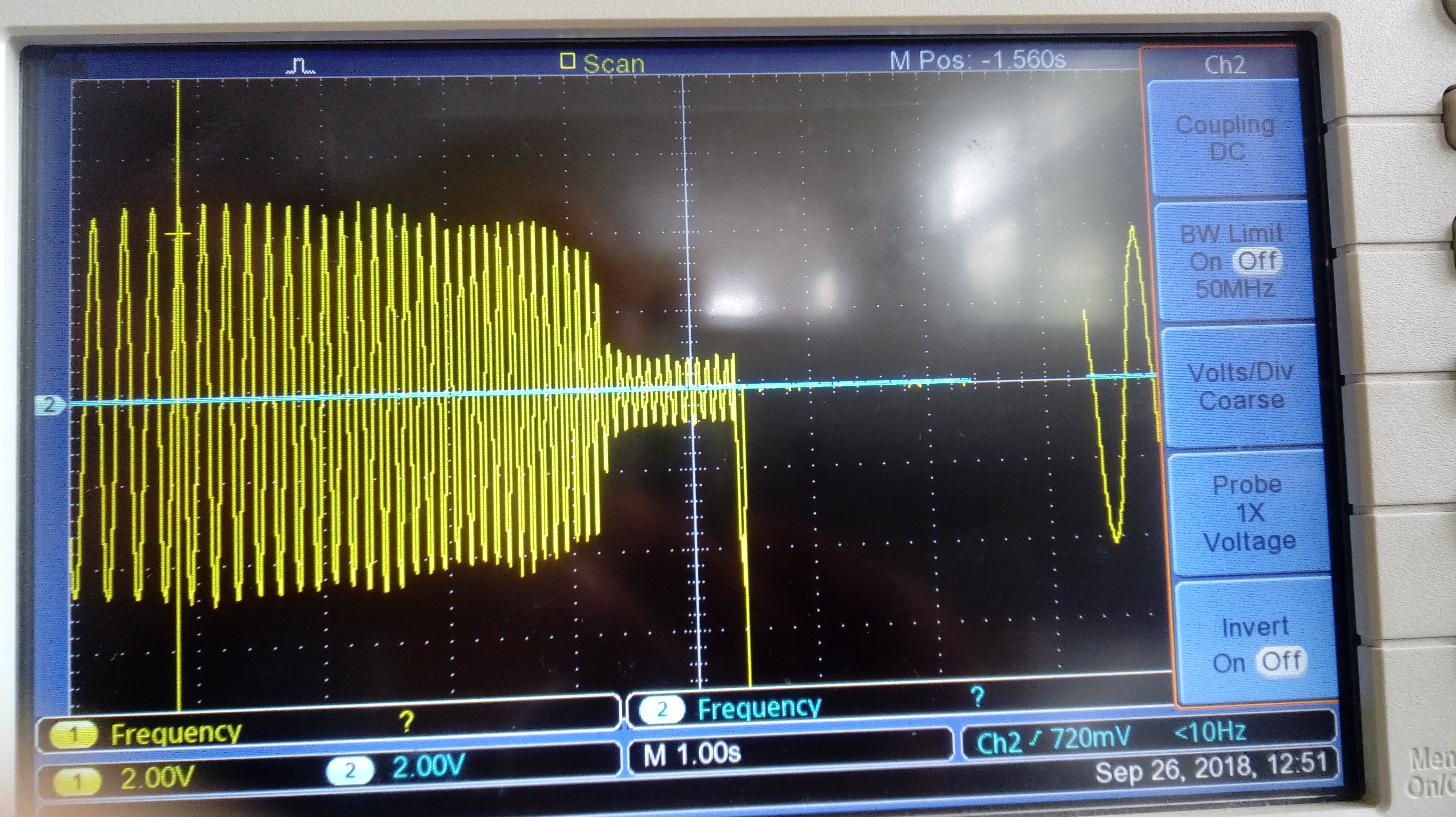
I am using DRV10983 for driving ceiling fan. Initially, i am rotating in open loop and i have disabled my close loop. The system starts with proper alignment time and with open to close loop threshold frequency it rotates for 5-10 seconds and then stops. I have measured Rm and Kt values using tunning guide as recommended by TI.

SYSTEM parameters:

Voltage: 24V

Current : 1.66A

Max Speed: 370rpm

Rm: 1.54 ohms

Kt: 692mV/Hz

initial speed:65% duty cycle

EEPROM data:

Address          Value

0x20         =         0xCA
0x21         =         0xEC
0x22         =         0xCC
0x23         =         0x03
0x24         =         0xC0
0x25         =         0x7F
0x26         =         0x52
0x27         =         0x14
0x28         =         0xEC
0x29         =         0x39
0x2A         =         0x03
0x2B         =         0x0F

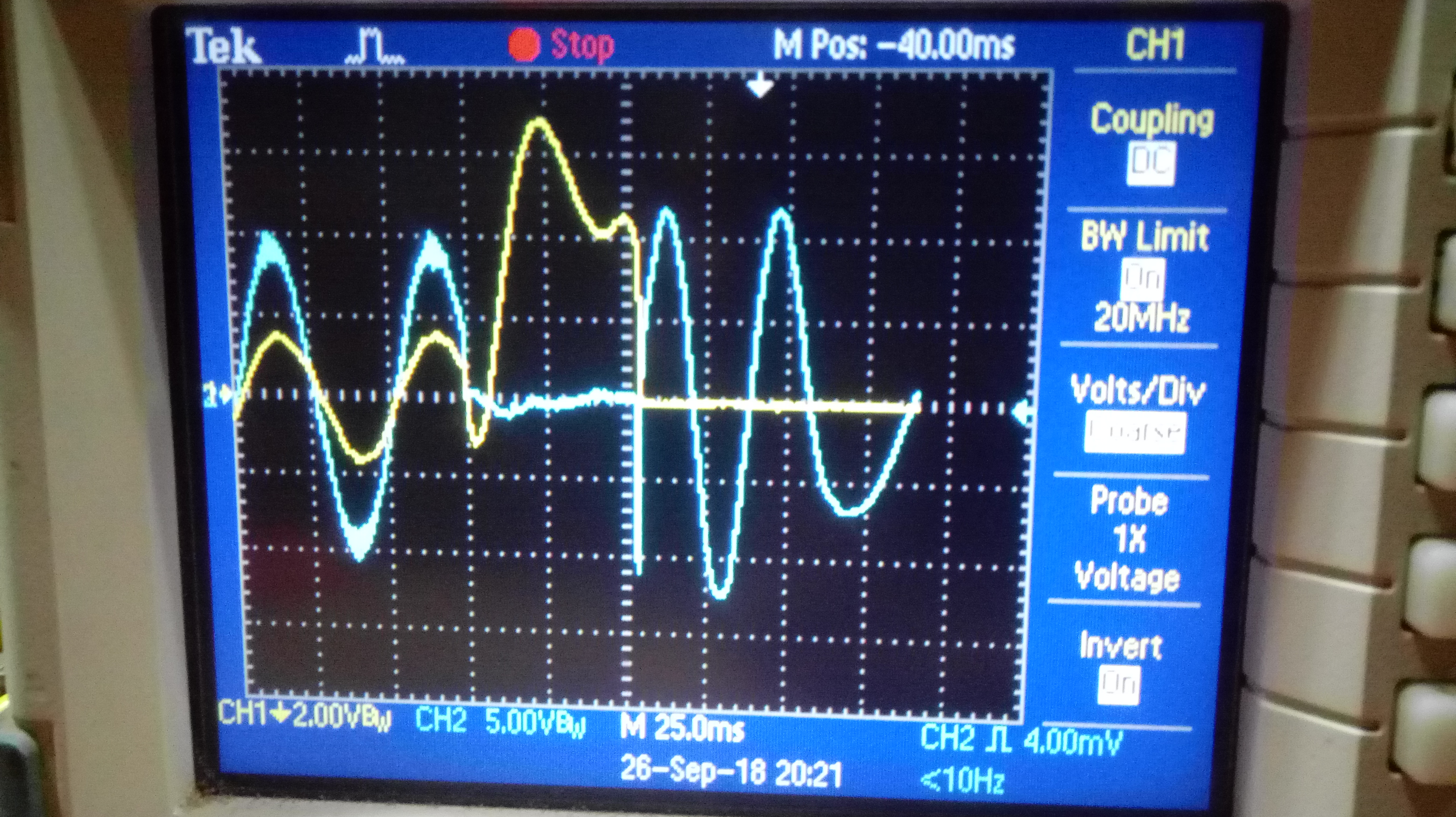
The above problem is with open loop. I have also tired to rotate in close loop. For close loop, speed above 70% duty cycle the system was working properly but for speed below 70% duty cycle (60% or 50% ) the system would run for 5 seconds and then stop indicating over current limit threshold. If i disable the over current limit threshold then to the fault will be same.

EEPROM data for close loop mode:

Address          Value

0x20         =         0xCA
0x21         =         0xEC
0x22         =         0xCC
0x23         =         0x03
0x24         =         0xC0
0x25         =         0x7F
0x26         =         0x52
0x27         =         0x14
0x28         =         0xEC
0x29         =         0x39
0x2A         =         0x03
0x2B         =         0x0E

  • Try and make your 0x27(address)   =   0x04(value).

  • Hey Vrajesh,

    Thanks for the suggestion i guess my open loop is working for 12 Hz open to close loop threshold frequency. But, when i change my system to close loop after achieving 12 Hz frequency the system doesn't work for duty cycle below 65%. Reading the fault register the overload current limit threshold fault shows high even if i had disabled the fault.
    Any idea for achieving speed above 50% to 70% duty cycle?
  • Jeet,

    It looks like you've disabled almost all of the locks. It is difficult to determine what is causing the issue with the locks disabled.

    I assume you've followed the tuning process in our tuning guide? www.ti.com/.../slou395d.pdf

    Higher handoff threshold will can result in better startup.

    Thanks,
    Brian
  • How is your motor status at duty 30% and 40%? Is it rotating reverse or something else?
  • Hey Vrajesh,

    In open loop currently at 12.5 Hz open to close loop threshold frequency the system is working fine and stable power losses are there but it's because it is in open loop. If i change it to close loop after achieving 12Hz frequency the system doesn't operate at any duty between 0 - 70% above 70% its working fine. If i try to increase my threshold open to close loop frequency to  25.6 Hz the system stops  just above 19Hz. 

    Thanks Vrajesh for replying, i guess with few conversations the system might run.

  • Hey Brian,
    In close loop, i tired enabling all the locks but the error was overload current limit threshold and even if i disable the error the status register would show me the overcurrent error. My system for duty less than 70% works fine for 1.5 minutes and then this error comes up and the system stops. In open loop, if i try to increase my open to close loop threshold frequency the system stops after 19 Hz frequency.
  •  The above image is current waveform the volt per division is 2 V and i have used a current probe with 3 turns so basically the volt per division is 0.66. For 30% duty the system start goes to threshold open to close loop frequency and then goes to close loop and stops and if i check the fault and status registers the fault register is 0x00 and the status register is 0x0F. So, the system is not in fault or lock but the motor stops.

    The below  image is current waveform the volt per division is 2 V and i have used a current probe with 3 turns so basically the volt per division is 0.66. For 40% duty the system start goes to threshold open to close loop frequency and then goes to close loop and stops and if i check the fault and status registers the fault register is 0x01 and the status register is 0x1F. So, the system goes to overload current fault and stops but i have kept the limit maximum and in waveform the current doesn't reach its limit.

    The 3rd image is current waveform the volt per division is 2 V and i have used a current probe with 3 turns so basically the volt per division is 0.66. For 60% duty the system start goes to threshold open to close loop frequency and then goes to close loop and stops and if i check the fault and status registers the fault register is 0x00 and the status register is 0x0F. So, the system is not in fault or lock but the motor stops.

  • Jeet,

    Thanks for the scope images. They are very useful.

    It looks like open loop operation is fine, but there is an issue when going to closed loop.

    2 Things I would try.

    1. Is there a reason you've set the control coefficient to 0.5? I would leave that at 1.0.

    2. I would adjust the lead time. I suspect that when we go to closed loop the lead time is not correct and we start miss commutating the motor and result in driving phases incorrectly which leads to high current.

    Thanks,

    Brian

  • Hey Brian,

    I have kept Control coefficient 0.5 in open loop and 1 after going to close loop.

    the lead time ( commutation control time is kept to 200us and if i go beyond the time system fails to decelerate. And the system is not stable as i can see oscillations in the current waveform.

    I have few questions:

    1. Is it recommended to operate always on open loop in low speed?

    2. Can i shift from close loop to open loop while spinning the motor( for low speed my system works well in open loop)?

    3. Is control coefficient use for open loop?

    4. i am attaching an image, in that image the voltage per phase ( blue)  and current line current for star system (yellow)  waveform is available. can i know why does the voltage shuts down and current shots up? this is the operation when i am in open loop i shift to close loop and after coming to close loop i provide 65% duty and system runs for 5 seconds and the failure occurs.

  • Jeet,

    I would leave the control coefficient at 1 for both open and closed loop operation. This is only used during closed loop operation.

    1. Are you asking if the acceleration rate should be slow in open loop? If so this is dependent on the inertia of the motor. The more inertia the slower the acceleration will need to be. For our IC open loop refers to blind commutation (commutation is not synced to the motor). Closed loop is when our algorithm is able to make the commutation decision based on BEMF.

    2. The IC should automatically change from open loop to closed loop based on the hand off frequency you've programmed.

    3. No. As stated above.

    4. I'm confused as to why your voltage is below ground? I would expect a PWM with varying duty cycle to generate a sinusoidal current. Until I understand the phase voltage I'm not able to comment on the phase current.

    Thanks,
    Brian
  • Hey Brian,

    Thank you for timely replies. With regards to our previous conversation, i have changed my control coefficient to 1 for open and close loop and the results are same. I will explain my system, initially my system is in open loop with current 0.8 (open loop current setting) but it consumes 1 A current if i see through oscilloscope. My system changes from open loop to close loop with handoff frequency of 12.8 Hz ( if i check through oscilloscope the frequency is 12.1 Hz) and with 65% PWM duty. System in close loop with 65% PWM duty spins for 5 seconds and shuts down with the same image as i have send above ( image with voltage and current waveform).

    The voltage waveform is sinusoidal as i have used RC filter ( cutoff frequency 5kHz). And we can see the voltage is in phase with current.

    My query is:

    1. Why does the system shuts down after 5 seconds at 65% PWM duty and why does it operates at 70% starting PWM duty( if i start at 70% duty instead of 65% duty at close loop) ? 

    2. Is the motor recommended to use at 30 - 70 % PWM duty?

  • Jeet,

    I overlooked one setting. Try changing the commutation control mode to constant time. This will apply the same lead time across motor speeds. Since current is less during low speed operation typically less lead angle is needed. By keeping the time constant the IC will actually apply a smaller lead angle at low speed and a higher lead angle at high speed.

    1. To confirm - if you apply 70% duty cycle the motor continues to spin, if you apply 65% the motor stops after 5 seconds. It looks like the motor is spinning very slow ~20Hz electrical rate. This isn't much above the hand off frequency. It does look like the IC looses synchronization with the motor. My first suspicion would be the lead time. Have you tried lowering it?

    2. Our IC should be able to drive the motor as low as a few Hz. Based on what I've seen of your system I would think 30-70% duty cycle would be ok.

    Thanks,
    Brian
  • Hey Brian,

    I could finally run my motor in close loop with 30-100% duty cycle. Previously, my DRV was malfunctioning as i had kept the DIR pin at high impedance.

    I have few queries:

    1. Are there any EEPROM registers or bits which i can use apart from the parameter bits? I need few EEPROM bits to store my data.

    2. What is the actual role of ISD?

    Thank you

  • Jeet,

    Glad you got it working!

    1. There really aren't any bits set aside for user information. However, if you don't use a featuer like ISD there would be a few configuration bits that could be used. For instance ISDTHr[1:0] and RvsDrThr[1:0]. Not sure if 4 bits are enough, but those could possibly be used.

    2. ISD is supposed to detect if the motor is already spinning. If it is spinning faster than the programmed threshold then it will automatically sync to the motor and start running (don't have to stop the motor and go through the align and open loop acceleration phases). If it is below the threshold it will stop the motor and then restart it.

    Thanks,
    Brian
  • Hey Brian,
    Still my ISD is not working properly.
    My motor is working fine with all the speeds. The motor, from standstill position rotates properly first, brake then align and go and then open loop to close loop perfectly. When i shut down my system and shut it on (the motor is spinning after i shut down as it is in inertia and thus has some frequency and with frequency around 10Hz, i shut the system ON) this time it takes 20-45 seconds and in this interval it reduces its speed or frequency to 0 Hz and starts again( brake then open loop and then close loop). So basically ISD operation didn't occurred.

    My EEPROM data are:

    Address Value

    0x20 = 0xCA
    0x21 = 0xEE
    0x22 = 0x1A
    0x23 = 0x08
    0x24 = 0xC5
    0x25 = 0xFD
    0x26 = 0x7F
    0x27 = 0xF0
    0x28 = 0xEF
    0x29 = 0xB9
    0x2A = 0x0B
    0x2B = 0x0E
  • Jeet,

    I'll close this thread since you have a similar one that Sanmesh is working.

    Thansk,
    Brian
  • Hi jeet,

    you have used your Kt=822mV/Hz.

    How did you calculate it?
    Does it match with tuning guide PDF page no 5 formula?(from pole pair and RPM).

    Because I'm suffering with same problem.
  • Hey Vrajesh,

    i have calculated it by referring to tuning guide page no 5. My calculated value is around 800mV/Hz so i choose 822mV/Hz. My major problem was i had kept my DIR pin in Hi impedance state so my motor was not working properly.