This thread has been locked.

If you have a related question, please click the "Ask a related question" button in the top right corner. The newly created question will be automatically linked to this question.

LMP91200 and EC probe

Other Parts Discussed in Thread: LMP91200, ADS1110, LM555

Hello!

I have some time using a chip LMP91200 in their projects. This is an excellent and easy solution for measuring pH. But recently I needed to add to the project measurement EC / ppm / TDS. And here I was faced with a big problem - for measuring pH the LMP91200 uses Buffered Programmable Common Mode output. This creates great difficulty for measuring EC to using AC. Ultimately, pH and EC measured incorrectly.

How to eliminate the influence LMP91200 on the measurement EC/ppm?

Best Regards,

Evgeniy

  • Hi Evgenly,

    I thoght about your issue. The liquid under test is forced to the potential of the VCM pin of the LMP91200, it means that when you try to execute another kind of measurement, such as EC, which forces the liquid to a different potential both measurements are wrong.

    I've in mind a solution, but it works only if your EC measurement requires one of the EC electrodes connected to GND.

    Let me explain:

    the pH probe needs to be connected between VOCM and INP instead of VCM and INP.  When you perform the EC measurement you have to configure the bit 7 of the Configuration register of the LMP91200 at 1. In this way VOCM is forced to GND and also the liquid under test is forced to GND.

    As wrote before it works only if one of the electrodes of the EC probes can be conencted to GND. For sure the 2 measurements pH and EC cannot be done in parallel.

    Please let me know if it helps.

    regards,

    Domenico.


  • Hi Domenico,

    thanks for the advice! I tested this method now. Unfortunately, it only solves the problem of reading the EC. With such a method of connecting the pH is read incorrectly (reading made ​​through ADS1110, EC circuit disconnected).
    However, a positive result is obtained when turning on/off the power entirely (gnd and vcc) alternately in the areas of reading PH and EC. It is not too comfortable, but it seems such a scheme can be implemented.
    In this regard, I have a new question - how to many on / off cycles intended LMP91200 and what is the minimum amount of time can be selected for this cycle?

    Best Regards,

    Evgeniy

  • Hi Evgeniy,

    There isn't any limitation on the times you can turn off and on of the device. Usually the time requested by the sistem to be ready to read the pH depends on the pH probe. Its output impedance and the parassitic capacitante on the board generate a low pass filter.

    just one more thing regarding the solution  I suggested. Is it possibile to connect the low side of the EC probe to the VOCM pin too ? In this way when you maesure  the pH the EC probe should not introduce any current in the system because you force VOCM=VCM and when you maesure the EC you force VOCM=GND.

    regards,

    Domenico

  • Hi Domenico,

    Many thanks for the advice! I double-checked the wiring diagram pH probe between INP and the VOCM contacts. And it looks like it really works! 

    I tried to use VCM as GND for the EC sensor. Here satisfactory results could not be reached.

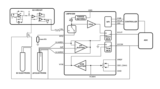
    I'm a little reinterpreted both council and I had the idea for a new hack LMP91200. See scheme:

    While I tried to apply a voltage to the resistor voltage divider to pin CAL. And at this point I got a sufficient scale to measure. And for this commutation sensors harmful interference excluded.
    What do you think about this circuit? Get access to the three sensors on one ADC seems very tempting


    Best Regards,

    Evgeniy

  • Hi Evgeniy,

    when you select the CAL channel, the LMP91200 tries to inject 100uA or 1mA (according to the configuration register) in your EC circuit, most likely it will reach the GND trough the filter connected to the super diode. If the voltage drop across the series resistance seen by CAL pin is less than VDD/PGA_gain and you have still some room for the signal it is fine.

    Maybe you could measure the voltage drop before adding the AC signal and subtract it from the total measurement. In this way you can remove the dependency from environment.

    Regarding the the measurement of the temperature with the RTD, it will be less accurate because you cannot use the calibration channel, but it could be enough.

    For sure the connection of the 3 sensors to one ADC is tricky, but if the system respects your constraints go ahead.

    regards,

    Domenico

  • Hi Domenico,

    thanks for pointing to the strength of the current in this part of the scheme. Indeed, now the oscillator op amp provides only 60 uA. But I found an interesting diagram of lm555. In one embodiment, EC can be read as a current from 0.2 mA to 1.5 mA.


    Detailed description here:
    http://emesystems.com/OL2mhos.htm

    PDF:
    http://www.emesystems.com/pdfs/SMX.pdf

    I think this element can be added to my circuit to read the EC through LMP21900. But I still need your help for solution of this task. By the way, why to pin CAL can not be fed 2 mA?
    I am satisfied to read data from the three sensors alternately at intervals up to half an hour. And besides, I like the compactness scheme on LMP. Temperature conditions all the time at the same level, and by and large in this situation pt100 sensor readings can be neglected.

    Please comment on this version of decision.

    Best Regards,

    Evgeniy

  • Hi Evgeniy,

    the Current at CAL pin can also be 200uA and 2mA. I didn't mention them just becasue I was refering to the order of magnitide of the current that the internal generator can source.

    The circuit shoul work, the DIS pin of the 555 should not have poroblem to sink current.

    regards,

    Domenico.