This thread has been locked.

If you have a related question, please click the "Ask a related question" button in the top right corner. The newly created question will be automatically linked to this question.

Connecting 4 3-wire RTD sensors in one ADS1248

Other Parts Discussed in Thread: ADS1248

Dear all,

I am trying to design a circuit for connecting 4 3-wire RTDs using ADS1248

Since the RTDs will be in a noisy environment having 5-6 meters cabling we will use RC filtering in ADC and REFERENCE inputs.

Is it possible to connect more than 2 sensors (with RC filters) to one ADS1248?

Thank you in advance!

  • yes, it is possible, as for Figure 114 of the datasheet...

    to connect the second one you have to use the other IEXCx/REFx pins via the internal muxes...

    hope this helped a bit

    KR
    Vincenzo
  • Dear Vicenzo,

    First of all I would like to thank you for your support!

    I am interested in connecting four 3-wire sensors on the same ads1248.

    Reading the manual and the application sheets I have the impression that only two 3-wire RTD's can be connected on the same ads1248!

    Is it possible to send you my design for verification and check?

    Best regards

    Nikos

  • yes of course you can...

    if you need to connect 4 RTDs then you would need 2 x ADS1248...

    you could also use the trick as for the attached app.notes, but the results you could get woiuld be very sensitive to the matching grade of the two line resistances...

    sbaa180.pdf

    sbaa201.pdf

    slau520a.pdf

    KR

    Vincenzo

  • Dear Vincenzo,

    I would like to thank you once more for your support!

    We would like to use 2 pH sensors and four 3-wire RTD's.

    For this reason we are focusing in using 2 ADS1248 for each pH sensor and two 3-wire RTD's using the following topology...

    Are there any recomendation in improoving this cirquitry?

    BR

    Nikos

    ADS1248_3wire-RTD & pH.pdf

  • hi Nikos,

    sorry for the late reply...
    it looks overall ok, just be aware that:
    - if not RTD is connected you have 0V reference so you can't sense the pH sensor as well
    - tha max REF voltage is VA - AN_GND - 1V, so having R46 = 3.3K means that the max IEXC is much less than 1mA; while if you are planning 1mA IEXC then you have to increase VA (that is decoupled from VD)
    - what's the purpose of R4 / R94, since that is not the normal position for the compensating resistors?
    - C6 nad C80 must be placed very close to IC47
    all the rest seems ok (I didn't enter in detail of the values because I don't know the details of your app)

    hope this helped a bit
    KR
    Vincenzo


    PS: please note that this forum is the wrong one, actually; for the ADS1248 you should consider the following e2e.ti.com/.../
  • ADS1248_3wire-RTD & pH (upd1).pdfHi Vicenzo,

    Our requirements are one pH sesnor (+/- 0.1 accuracy) - two 3-wire RTD's (0-50 oC 0.1 oC accuracy) sampling rate 5Hz!

    The sampling procedure will be

     - pH:      (a) Turn On VREF

                     (b) Read pH (AIN1 - AIN0)

     - RTD1: (a) Turn On IEXC1 & IEXC2

                     (b) Read RTD_1 (AIN3 - AIN2)

     - RTD2: (a) Turn On IEXC4 & IEXC5

                     (b) Read RTD_1 (AIN7 - AIN6)

    (-if not RTD is connected you have 0V reference so you can't sense the pH sensor as well)

    The ADS1248 VREF will be used for pH amp VREF, so  REFP0 & REFN0 are disconnected from VREFOUT & VREFCOM!

    (- tha max REF voltage is VA - AN_GND - 1V, so having R46 = 3.3K means that the max IEXC is much less than 1mA; while if you are planning 1mA IEXC then you have to increase VA (that is decoupled from VD))

    Updated to 820R!

    (- what's the purpose of R4 / R94, since that is not the normal position for the compensating resistors?)

    They are for compansation! (Corrected!)

    (- C6 nad C80 must be placed very close to IC47)

    C6 & C80 or C74 & C42?

    Also, should I open a new topic to ADS 1248? Could you transfer this topic?

    Thank you very much!

    Nikos

  • Dear Vincenzo,

    In the previous post the schematic have been updated/corrected taking into consideration your comments.

    Reading again the appnotes for ADS family I am confused i little bit with the compensation resistor.

    I have the feeling that in the upd1 schematic the compensation resistors are not connected properly and the upd2 are closer to the appnotes (like tidu145).

    Could you please advice on this issue?


    Best regards,

    Nikos

    ADS1248_3wire-RTD & pH (upd2).pdf

  • Hi Nikos,

    Please allow me to add some comments to your questions as Vincenzo is currently out of the office.

    It seems that your design is pretty much in accordance to the TI Design TIDU145 which is based on a Hardware-Compensated Ratiometric approach. I have reviewed your schematics. I assume that you are going to use PT-100 RTDs in your design for a temp range of 0-50°C. Below some design considerations that need to be taken into account:

    - Rcomp resistance: Has to be equal to the resistance of the PT-100 sensor at +25°C (mid-scale). In your Design you are using Rcomp = 110 ohm which is fine for a temp range of 0-50°C using PT-100 RTD.

    - Rcomp location: Should be placed in series with the negative ADC input with the second current source, I2, flowing through it. This is placed correctly in your design.

    - Selecting IDAC values: The magnitude of the current sources directly affects the magnitude of the RTD voltage. While maximizing the magnitude of the excitation current would seem desirable, higher excitation currents create a concern for violating the compliance voltage of the current source as well as errors due to self-heating. Here the recommendation is to start with 250uA to 1mA max.

    - Selecting Rref: Select Rref such that Vref is ~40% to 50% of AVDD. In your design AVDD is at 3.3V so that Vref should be at around 1.65V. Rref should be chosen with tight tolerance and low temperature drift: 

    • DC errors in Rref directly affect the uncalibrated measurement gain error
    • Typical drift for Rref = 5 – 20ppm/°C

    - The value of Rref is selected based on the IDAC setting and the desired VREF voltage of 1.65 V @ 3.3V AVDD

    - For a 250uA IDAC current Rref = 1.65V / (2x250uA) = 3.3k ohm

    - RTD input and reference filters should have matching cutoff frequencies

    - PGA Gain: You need to select the highest gain to get the best resolution per °C.  The big concern is not taking the gain so high that the measurement at the highest temperatures is greater than the reference voltage. 

    - Further, you need to make sure that the input common-mode voltage is not in violation with respect to the desired gain.

    - Turn internal VREF ON, otherwise IDACs will not work.

    - Start a measurement only after the input signal has settled. Especially important when MUX'ing channels.

    - If a data rate of 20sps or less is used, you can take advantage of the simultaneous 50/60Hz power line cycle rejection on the ADS1248.  This noise can be picked up on the leads of the RTD wire.

    Hope this will information will be helpful otherwise please let me know.

    Kind Regards,

    Mo.

  • All,

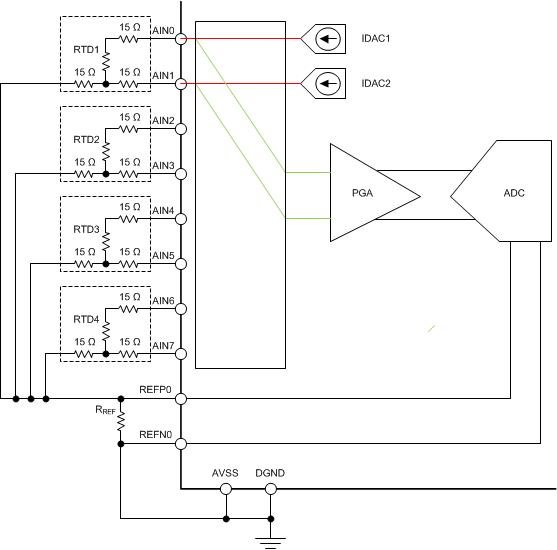
    I just happened to find this thread today about using four 3-wire RTDs.

    There is a way to measure four 3-wire RTDs with the ADS1248. Included below is a diagram:


    It is very important to note that this configuration does not allow for input filtering. Any series resistance mismatch (like input filtering resistors will give large errors). There are 15Ω resistors shown to represent the wire resistances.

    If you don't need the filter resistors, then this can be done. However, if you do need filter resistors, then I would use your current schematic.


    Joseph Wu

  • Nikolaos,


    Now that I've had a chance to look your schematic, I did have a few comments.

    1. Right now, it looks like you have separate analog and digital grounds. In general, we like to use a common ground whenever possible. Just consider the analog and digital return current paths so that you don't have large ground loop voltages.

    2. It looks like you have two 110Ω resistors for hardware compensation. This would be R4 and R94. I recommend NOT using hardware compensation. You might be trying to increase the resolution by centering the measurement, but in practice, this is very difficult to achieve. You need to consider both the accuracy of the 110Ω resistor and the amount of drift that this resistor has. When you do try to apply hardware compensation, it often performs much worse than you might expect because of the accuracy of this resistor.

    3. I'm not very experienced with the supply circuitry, but I always note that circuits with inductors in the supply paths may be problematic. Because of the nature digital circuits, there are large current spikes, which leads to large voltage spikes. The voltage goes as Ldi/dt and you may disrupt digital specifications and I've seen problems with that in the past.


    Joseph Wu
  • Dear Mo,

    Thank you very much for your support!

    Indeed my design is very close with TIDU145 which includes a resistor in one of the input channels for hardware compensation. I was wondering for compensation resistor accuracy issues from the very beginning of the design and finally after and Mr Wu advice (latest post) I will remove the hardware compensation resistors (R4 & R94).

    I am planning to use 1mA IDAC currents (taking into consideration the temperature range 0-50oC). For this reason in the upd2 schematic the REF resistor reduced from 3K3 to 820R. Do you believe that I have to stay with the initial design using 3K3 REF resistor?

    Also I was confused with Vincenzo advice on the initial design "if no RTD is connected you have 0V reference so you can't sense the pH sensor as well". Do you believe that there is an issue in the upd2 design with VREF in pH measurement if  RTD's are not connected?

    Best regards,

    Nikos

  • Dear Joseph,

    Thank you very much for your support!

    I was wondering about the use of the two compensation resistors from the very beginning of the design and your advice really helps me to decide about removing them!

    The two inductors are used in TI design tidu145. Additionaly there are 10uF capacitors in parallel with 100nF decoupling capacitors in analog and digital power lines. Do you believe that its better the two inductors to be removed?

    Best regards,

    Nikos
  • Nikos,


    Since it's in the TI design, I would leave them in for the time being. I'm just concerned that with digital currents, you might see more supply spiking. You can still test it to see if it poses any problems. Later, it should be easy to alter the design to remove them.


    Joseph Wu
  • Dear Joseph,

    I wll keep it mind during the prototype testing.
    Thank you very much for yur support!

    Nikos
  • Hi Nikos,

    Nikolaos Piliouras said:
    I am planning to use 1mA IDAC currents (taking into consideration the temperature range 0-50oC). For this reason in the upd2 schematic the REF resistor reduced from 3K3 to 820R. Do you believe that I have to stay with the initial design using 3K3 REF resistor?

    Increasing the IDAC current to 1mA will not violate the IDAC compliance voltage @3.3V AVDD in your configuration. Below the Math:

    Vcomp = AVDD - 0.7V = 2.6V

    VIDAC1 = Vref + Vrtd(max) < 2.6V, with Rrtd(50°C) = 120 ohm, Vrtd(50°C) = 120 ohm x 1mA = 0.12V

    VIDAC1 = 820 ohm x 2 x 1mA + 0.12V = 1.76V < 2.6V, good!

    Now to the self-heating effect. Increasing the IDAC current will increase errors due to the self-heating of the RTD. The effects of self-heating on measurement accuracy are also based on the placement of the RTD in the application (open-air = insulates vs. moving fluid = dissipates). If this error -depending on your RTD type- is very little and negligible in your design and it can be tolerated that then that's okay!

    Nikolaos Piliouras said:
    Also I was confused with Vincenzo advice on the initial design "if no RTD is connected you have 0V reference so you can't sense the pH sensor as well". Do you believe that there is an issue in the upd2 design with VREF in pH measurement if  RTD's are not connected?

    If no RTD is connected then there will be no voltage created over Rref, hence no external Vref will be available. However, you can still use the internal generated Vref (2.048V) for your pH measurements.

    Kind Regards,

    Mo.

  • Nikos,


    There are two things that I wanted to point out about Mo's comments. First, he is correct that you should watch the compliance of the output voltage of the IDAC current to AVDD. If you get to close to AVDD, then the IDAC current will start to decrease. Second, the compliance of 0.7V to AVDD is a bit optimisitic. This was in previous revisions of the datasheet, but in the current revision of the datasheet, we simply refer to Figures 41 and 42.

    I would also note that it likely will not be a problem. If there is no current leakage path out of the RTD and RREF measurement, then the ratiometric measurement still holds, regardless of the current. You should still be able to get a useful measurement out of the device.


    Joseph Wu
  • Dear Mo and Joseph,

    Thank you so much for your support!

    Nikos