This thread has been locked.

If you have a related question, please click the "Ask a related question" button in the top right corner. The newly created question will be automatically linked to this question.

AFE5805EVM + TSW1250

Other Parts Discussed in Thread: AFE5805EVM, AFE5805, AFE5809

Hi,

We've connected these two evaluation modules, installed LabView 7.1, then installed the required software for these two modules.

We are using the onboard 40MHz clock. Therefore, we shortened jumpers according to figure 4 on page 5 of "User's Guide SLOU222B–March 2008–Revised November".

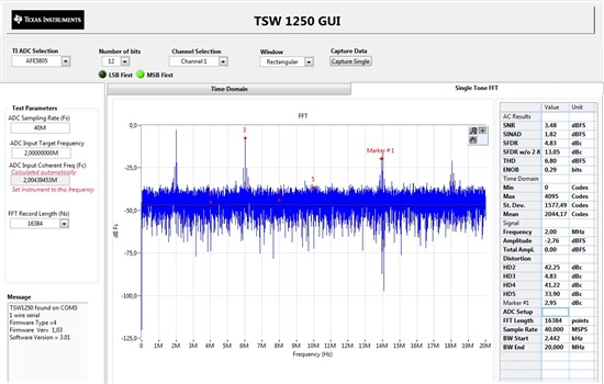
It now (after a long series of tries) can acquire new signals when we click on "Capture" button, but we get only noise.

We use a 2MHz pulse generator, but can not recognize any peak at that frequency.

We use only one channel (CH 1) from  AFE5805EVM .

Our settings for the "TI ADC SPI interface " are:

ADC:  Address byte: 46, Data bytes: 8208, "power down" is "off" only for CH 1. "LOW FREQ. NOISE SUPP" is "on" only for CH 1. "Gain" is 12 for ch 1 and 0 for all other channels.

VCA: THE BUTTONS ARE SHOWING : power on, TGC, BP filter 15MHz, no clamp, PGA gain 30 dB,

Our settings for the "TSW 1250 GUI " are:

AFE5805, CHANNEL 1, Hanning, ADC sampling rate 40 MHz, ADC input freq 2MHz, FFT record length 65536.

Our wonder why we just get noise.

Anything is missing? What?

The tables and figures are not consistent. It is very hard to know for example which jumper we should short when we get the message "jumper settings for rev B: JP2 = short 1-2,  JP8=SHORT 1-2, JP9= SHORT 1-2"

We spent a lot of time on just trying to make it work properly. The information provided by the two pdf-documents is not enough.

We need assistance ASAP.

Thanks in advance,

Satya

  • Hello,

    I have the same problem.

    I only can see noise, while it is possible to see a number of peaks when I use an oscilloscope (it can compute FFT).

    Any idea why it acquires just noise. As if no signal generator is connected to it?

    sincerely,

    hamed

  • Satya,

    In my first test, I had the same problem.

    - Did you conected the -+5V power suply to the AFE5805 eval board?

    - Verify the presence of the internal oscilator jumpers, my board come without them! (look beside the oscilator) (two jumpers)

    - Use the three magical commands throug the AFE software before start the FFT application. (i don't remember the addres and byte, but they are on the user guide).

    -Disable cutoff voltage.

    Let me know if you move on. I'm using the same board.

    Best regards,

    Roger


  • Thnank you Mr.Roger.

     Today I'm going to test it again.I had given both +5v and -5v. and I had setup the jumpers but thing is that I got result in the first time but later  it shows error   I did not Understand what has happend. I had installed labview7.1 is it ok or I need install some other version.


    Thank you advance,

    Regards,

     satya.au@gmail.com

  • Satya,

    I've installed the software from the CD that come with the EVM. But I had some timeouts, then I've download the last version V1.04 from Texas website.

    http://www.ti.com/lit/zip/sloc142

    I don't have LabView in my machine. I've install the software in a fresh win XP instalation. But I've noted that the EVM software install a National MAX and some runtime stuffs.

    Now it is working very well, I'm using a function generator straight in the AFE board ch1, without filter and is showing a nice pick in FFT at 2MHz.

    Take care with the white wave shown in the Time domain screen. This unwrapped wave is always messed, but the red 'real' wave is OK.

    Are you planning to modify the TSW1250 code? keep me posted.

    Best Regards,

    Roger

    Ps.:  The AFE respond better to a signal lower than 10mVpp.


  • Dear Rojer, 

    Now I got time out problems and 

    I got special problem with I dont Understand

    Error with TSW1250
    Communication.
    Reset the FPGA Board.


    I used onboard 40MHz for that I made jumers short.I dont understand. what was my mistake.

    and may I know what are you doing with this instrument???????????


    Thank you advance,

    satya.

  • The time out is due to FPGA capture error. it happens due to no ADC output, loose connector, random timing error.

    when you see this error, you can power down the TSW1250 and restart TSW1250 GUI. Make sure the AFE5805 EVM current consumption is about 0.4A, i.e. ADC in the AFE is working normally with a correct ADC clock in.  then everything should be normal.

    Thanks!


    Xiaochen

  • Hello, where can I buy the power supply? I did not find it the module package... Can I buy it from TI's online store? Thank you!!

  • I'm with the same problem (my capture are getting just noise). After so many time did anyone solve this?

    Thank you

  • Danilo, 

    from the previous posts, people figured out the problem. some are due to wrong setting; some are due to out of date software. i believe TI stopped shipping CD in EVMs. you can always download latest software from TI web. 

    the 5V current  will help you jduge if EVM is in right mode. 0.4A current should be drawn from 5V supply. 

    User manaul states below on AFE5805EVM GUI: 

    1. Set Address Byte(s) = 0 Data Byte(s) = 1. Click any space area to send command to AFE5805.
    2. Set Address Byte(s) = 42 Data Byte(s) = 8081. Click any space area.
    3. Set Address Byte(s) = 46 Data Byte(s) = 8208. Click any space area.

    could you post a noise plot? are they random noise around DC or others? 

    Thanks!

  • To get this signal above I used a 2MHz sine wave, 100mVpp.

    I will need to get the 8ch at the same time. Is that possible? Do you have the original verilog code to I start to chance for my project?

    Thanks

    Danilo

  • Please order TSW1400 if you would like to capture 8CH simultaneously.  you may request TSW1400 firmware on e2e. 

    please make sure the input amplitude doesn't saturate ADC, which accepts up to 2Vpp input.

    AFE5805 EVM default gain is set around 45dB or 35dB, depending on PGA setting. 

    Thanks!

  • the AFE5805 is able to acquiring 8ch simultaneously? If yes, there any other solution to I use the TSW1250? I will need to do my own code for the FPGA, because I will need controlling emissions delays to create a beamforming.

  • AFE5805 is a 8CH device and all 8CHs are running at the same time, it was released in 2008. the latest AFE is AFE5809. 

    i attached the TSW1250 FPGA code. you can look at them and see if they are helpful. 

    we will obselete TSW1250 very soon.  we can just provide the code as is. no support will be provided. 

     TSW1400 will be the replacement for TSW1250. 

    Good luck!

    8546.DeSerTSW1250 Customer Version.zip

  • ok. Another doubt, do you have a board to make the emission? I need that it be 8ch too, and I intent to control all by the TSW1400 FPGA.

    What do you think is the best board for my purpose?

    Thanks

    Danilo

  • Hi Danilo,
    I write the verilog code with the AFE5805,can you help me look it?
    Thanks!
  • my email is 1044233591@qq.com