This thread has been locked.

If you have a related question, please click the "Ask a related question" button in the top right corner. The newly created question will be automatically linked to this question.

A peak interference phenomenon using LM96551/LM96530/AFE5803

Other Parts Discussed in Thread: AFE5803

Hi,

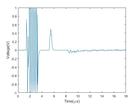
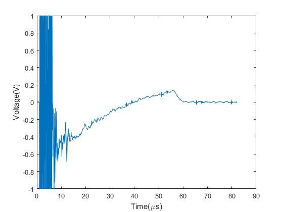
I'm using  LM96551/LM96530/AFE5803 to build a prototype. 8 channels of the LM96551 were parallel connected to excite a 2000pF ultrasound transducer. A picture below shows a received signal. A +50V and -50V pulser excite at the 1us. Then reflected shock lasts about 2us (from 1us to 3us). The amplifier seems not working in the range from the 3us to 8us.  However, the received signal has a peak interference at 6us. The problem is that I cannot use the signal before 8us. Can anyone help me solve this problem?

I also capture the signal before and after the LM96530. Channel 1 is the signal after LM96530 and Channel 2 is the signal before LM96530.

  • Hello,

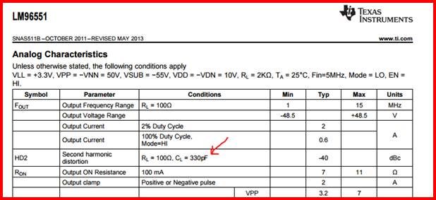
    I've got a question regarding the load that the LM96551 sees in your system. You mentioned 2,000pF ultrasound transducer while we anticipate from 200-300pF for the equivalent capacitive load!

    Can you please confirm that you are in fact working with that high a transducer capacitance?

    Regards,

    Hooman

  • Hi,

    Hooman. Thanks for your reply. I'm sure we use a single element ultrasound transducer with a 2000pF capacitive load. That is why we use eight channels of the LM96551 parallel to increase the drive capability. After LM96530 we found a DC offset low frequency noise which may cause this problem.

  • Hi,

    Here are some suggestions:

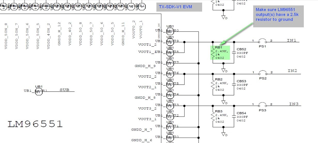
    1. Add 2.5k resistor to ground on each LM96551 output pin, as shown below. The internal clamping diode(s) on each LM96551 output (see Block Diagram image in the datasheet) work better if a DC path to ground exists.

    2. Add a similar resistor to each LM96530 output to ground in order to alleviate any DC offset that might be created due to the mismatch of the internal diode bridge (see Block diagram image in the datasheet) leakage current(s):

    You can see these same resistors incorporated in the TX-SDK-1 EVM zip file schematic (where images above come from):

    Also, please make sure that you AC couple the LM96530 output(s) to the AFE5803 (if not already?).

    Regards,

    Hooman

  • Hi, Hooman

    Thank you very much for your reply. Yes, the LM96530 outputs are AC coupled to the AFE5803. You give me really good suggestions from hardware view. I will change the values of the two resistors you mentioned. And the AFE5803 also has high pass filters in side. The AC coupling capacitor can effect the cut-off frequency. But it can not remove the low frequency noise completely. Is it necessary to do high pass in the software?

    Best,

    Phx

  • Hello,
    Unfortunately I'm not familiar with the operation of the AFE5803 and I cannot answer whether or not you need to do any high pass filtering in the software.
    Hopefully other people more familiar with the AFE5803 in this forum and can respond to your question.

    Regards,
    Hooman
  • Phx,


    The AFE5803 has an AC coupled input and variable HPF in the LNA.  The ADC also has a digital HPF.  The analog HPF is recommended but let me know if you need to reduce the cut-off frequency.


    Thanks,

    Chuck Smyth

  • Hi,Chuck Smyth,

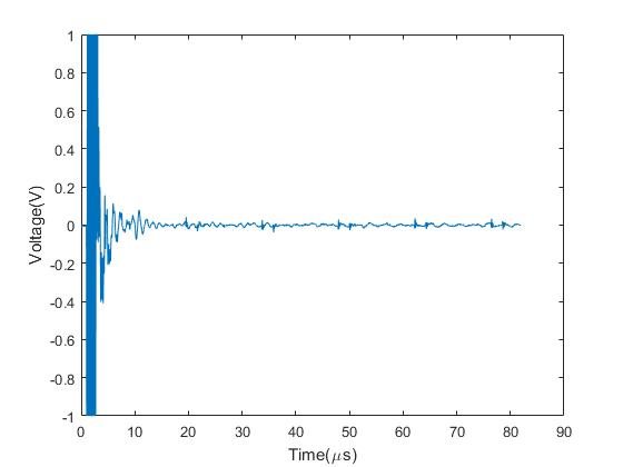
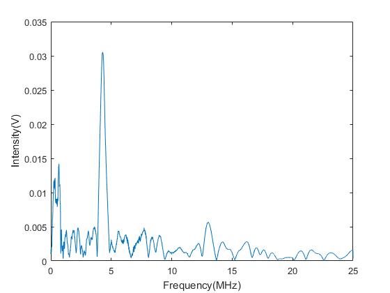
    Thank you for your kind help. The picture below is a 5MHz single excitation with the digital HPF function turned on. It seems work fine. 

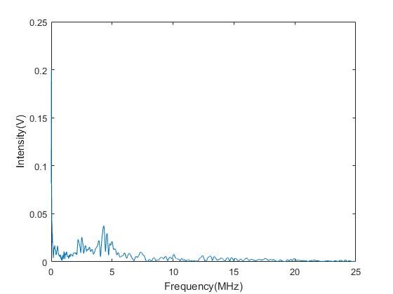
    However, when I use coded excitation. The low frequency noise becomes large.

    It becomes larger when the coded length increases.