This thread has been locked.

If you have a related question, please click the "Ask a related question" button in the top right corner. The newly created question will be automatically linked to this question.

AFE5808A clock input capacitance

Other Parts Discussed in Thread: AFE5808A

Can you please tell me the differential and common-mode input capacitances and their tolerance for the AFE5808A ADC clock? I have a long string of these parts driven by a sine wave clock, and it appears that these capacitances are much larger than what I expected from a bipolar comparator (e.g. 1 pF), perhaps due to the use of MOS instead, and so the net transfer function is off from my prediction. I should be able to correct for this though if I had a better understanding of the ADC clock input loading.

Thanks,

Roger Dixon

  • Hello Roger,

    How are you?

    Thanks for using our AFE5808A device.

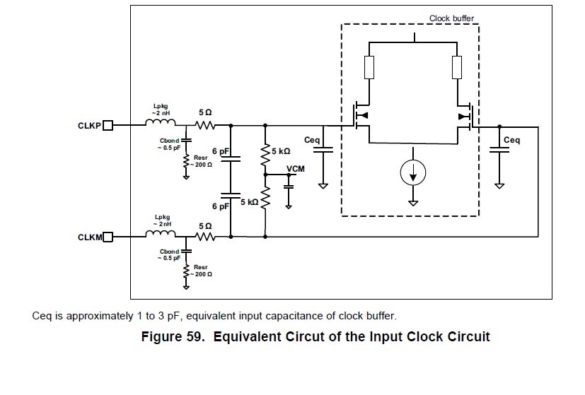
    For AFE5808A input clock the equivalent input capacitance is around 1 to 3pF.

    Please look at the similar equivalent circuit shown as below.

    Since the AFE5808A clock freq max is 65MHz (from the data sheet),

    it won't be affected by the input capacitance at all.

    When you are using a sine wave clock to run ADC clock input,

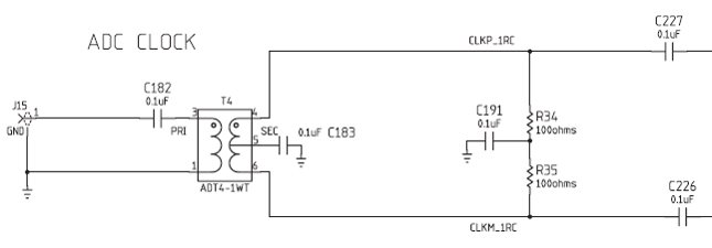
    the AFE5808A user's guide suggests to use AC-coupling for the clock-in

    by connecting 0.1uF (such as C227 and C226 below) in series. Please see the following schematic from the user's guide:

    Thank you very much.

    Best regards,

    Chen

  • Hello Roger,

    How are you?

    As you can see from the equivalent circuit of the clock diagram for

    the differential clock input signals (CLK+ and CLK-) of AFE5808A device.

    Their clock input impedances are not infinite high (although they are high)

    and also their values are related to your input freq as well.

    Thank you very much.

    Best regards,

    Chen

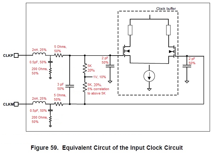
  • Sorry Chen, I didn't mean to ignore you and this thread but I lapsed into an email chain with Xiaochen. Thanks for the help, and in case anyone else needs it below is the input model with all of the tolerances.

    Roger