Dear all,
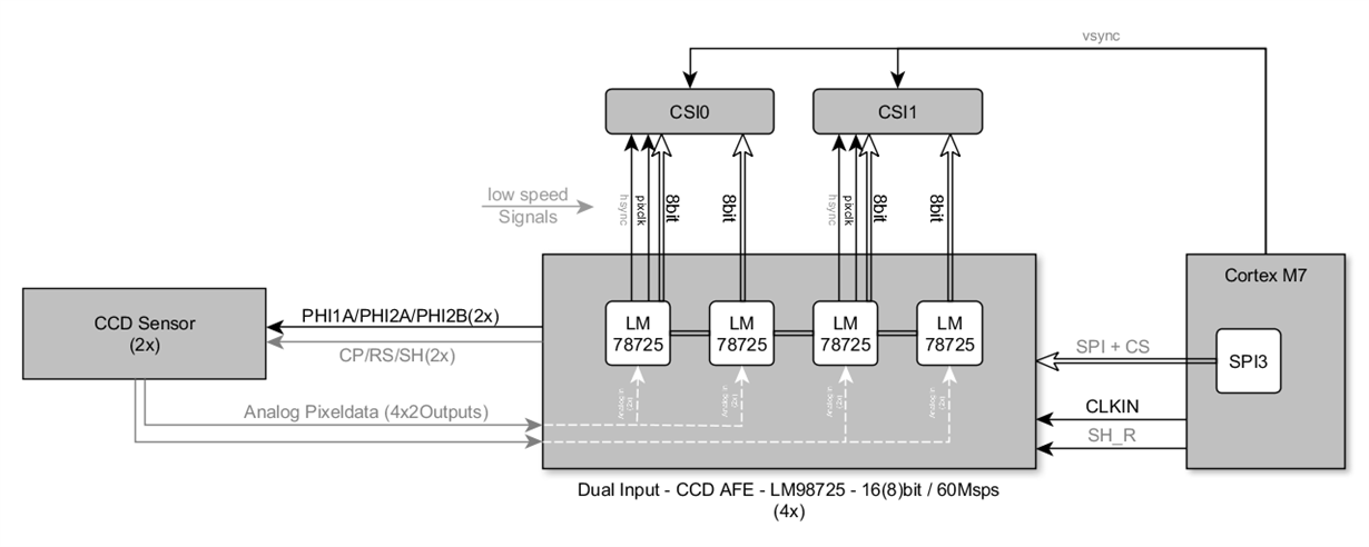
we have a processor in our design which will deliver the base IN_CLOCK for the two Analog Front-Ends LM98725. One Analog Front End itself will lock the internal PLL to achive some desired internal frequency. From that internal clock, the OUTPUT_CLOCK for the parallel Data Interface will be derived.
As we already integrated two of these LM98725 in our design, since our CCD sensor has 4 analog outputs, there is one question left:
Let me assume now, that the internal PLLs are locked.
So my question is, if both PLLs from the two AFEs will lock in the same phase, to ensure that the output clock for the parallel Data Interface of both Analog Front Ends (which may be up to 60MHz) will also be in phase?
I am afraid that in this configuration the OUTPUT_CLOCK of the AFEs may not be in the same phase, since the IN_Clock for the AFE is only 30MHz or less, and the PLL might be locked but with different phases in the two AFEs.
I attached a small drawing showing the setup, with 2 CCD Sensors which sums up to 8 Analog Outputs in total.
("low speed Signals" are only the hsync signals, see fig.)


