This thread has been locked.

If you have a related question, please click the "Ask a related question" button in the top right corner. The newly created question will be automatically linked to this question.

LM98725 PLL Unlock

Other Parts Discussed in Thread: LM98725

Dear. experts

I'm using LM98725 on MFP scanner.

I have few question about it.

1. When I start MFP and LM98725, sometimes the PLL don't get locked.

    But if I restart MFP, it works well.

    Have you ever had any issue about pll unlock? If you had, how did you solve this problem?   

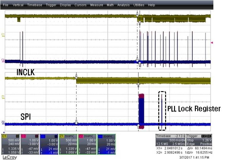
    - INCLK is not stopped, when SoC is writting value of register by SPI.

2. On datasheet page 6, 6.1 absolute maximum ratings, the soldering temperature is max. 235℃.

    If package temperature of AFE is exceed 235℃ during reflowing, is LM98725 possible to be damaged?

    I did ABA test, it looks like AFE has been damage, sometimes the PLL don't get locked.

Sorry about my bad English, please reply about my question.

Best Regard.

  • Hello Hyungsung,

    TI does not guarantee the device to be operational if the absolute maximum ratings are exceeded. If the LM98725 experiences temperatures higher than 235 C, it is possible that it is damaged.

    Please ensure you are soldering the device according to the datasheet limits. Please let me know if you have any issues after that.
  • Hello James

    I adjusted reflow temperature under 235℃, but still occur same problem (PLL unlock).

    After power on, during calibration scan, pll unlock occurs.

    But it occurs not everytime, about 1 of 500 time power off->on.

    So please check about the timing of Serial Interface and INCLK.

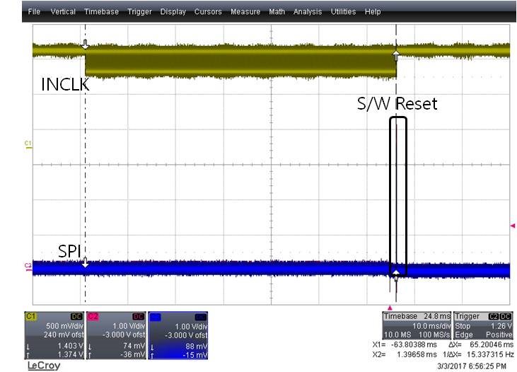
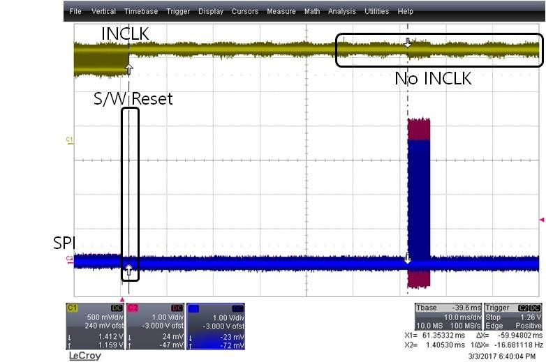
    1. After powrer on, INCLK Start, wait for 65ms, and write software reset by serial interface communication.

    2. After software reset, wait for 59.9ms, and write AFE initial register setting by serial interface communication.

        During write AFE initial register setting, there's no INCLK.

    3. During calibration scan, after INCLK start, wait for 60ms, and serial interface communication start.

  • Hyungsung,

    Since you observe the error infrequently and only at power up, I wonder if it is related to somehow to your supply rails. Are you powering all the supply rails of the device with 3.0-3.6 V, and do all supply rails power up at the same time? Are all the decoupling capacitors set to the values recommended by the datasheet? Are there any transients that appear at power-up?

    One thing you can do is to assert the RESETn pin low after power-on. That should ensure device operation if the issue is power supply related. Are you doing that now?

    Additionally, I found a couple other E2E posts about PLL locking for this device. Do either of these help you?

  • Dear. James

    I'm not using RESETn pin.

    I have question about RESETn pin.

    How long is the minimum time of maintaining RESETn low?

    There's no information of RESETn timming on datasheet.

    please reply.

    best regard

  • The Serial Interface Timing Specifications should be good to use for RESETn. This sets the minimum time to 4 ns (Input Hold + Input Setup), so choose a time greater than this (maybe double). If you can hold it for as long as 1 ms, that should guarantee the device is properly reset.

  • Dear James

    I have question.

    1. In 8. March, I showed you some waveforms. Are they correct?

    2. I want to know about correction between power sequence and PLL lock. Could you explain?
  • Hyungsung,

    1) Unfortunately I cannot verify the waveforms. These are old devices from National Semiconductor, and we no longer have the evaluation boards for me to check on my lab bench.

    2) Sometimes devices with multiple supplies do not operate correctly if the power supplies experience some issue at power-up (transient, ramping out of order, etc.). If you try asserting the RESETn pin, this should clear any issues, power-up or otherwise, from the device. Have you had better success with the RESETn pin?