NOTE: This post is duplicated in the following link (the forum didn't let me post the thread linked to the LM98725 part in the "Imaging AFEs Forum"): e2e.ti.com/.../620332
Hello everyone,
we have a CCD sensor that outputs 4 analog signals, which are connected to 2 LM98725s (to 2 channels in each AFE), that output the data in the CMOS output format from the DOUT pins.
Both of the AFEs get the same INCLK (runs at ADC clock, i.e. 2x CCD clock) and SH_R, they get the same control register values and both generate the same control signals, but just the first one's control signal pins are connected to the CCD sensor (the second AFE's control output pins are unconnected). The AFEs use CDS sampling mode. Only the high-byte of each CMOS output is used (i.e. producing 8bit pixel values).
Most of the time the data that we get from all 16 DOUT pins is correct, but sometimes in the second AFE we get dead frames. In this faulty state, the AFE randomly creates dead frames, where the CMOS outputs give zeros (0x00) for the whole frame.
This faulty state happens just in 2% of the cases after reset and init of the entire device, and then it remains failing randomly until the next reset.
In the remaining 98% of the cases after reset and init of the device, everything works consistently and correct.
The only way to recover from the faulty state without resetting the whole device is by resetting the state machines AND the registers of the AFE (via register command), and then sending the same register values that it had in the faulty state (resetting only the state machine does not help).
However, all the control signals are correct (even though they are not used), and if we read all the registers and compare them with the first AFE (which works correctly), all of them match (except individual PGA and ADAC offset values).
This consistently happens only to AFE #2, but never to #1, also in other prototypes of the same hardware.
Both AFEs are essentially connected in the same way, however, only the control signals of AFE #1 are forwarded (both for the CCD sensor and for the camera interface), and AFE #2 is only sampling the signals based on the same input clock.
Note that if fixed AFE CMOS output test values are selected (via register settings), the correct values appear in the digital outputs also in the faulty state.
Concluding from that, it appears as if all function blocks within AFE #2 work (SH and high speed signal generation, input sampling), but the AD conversion has some sort of random problem, resulting in randomly created "dead" frames of value "0x00" for the entire sensor frame...
I'd like to know if you have ever seen such effect with the LM98725, and if the fact that the control signals are not connected in the AFE #2 could have any negative influence in it.
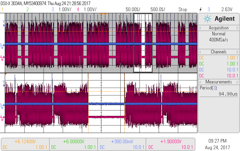
The attached figure shows the SH_R signal (in blue) sending a pulse every 95us and the DOUT6 (pink), where the dead frames can be appreciated every now and then.
Thanks in advance.
Best regards,
Inaki Lujambio


