• Join
  • Sign In with my.TI Login
Texas Instruments
  • Products
  • Applications
  • Tools & Software
  • Support & Community
  • Sample & Buy
  • About TI
Sample & Purchase Cart Sample & Purchase Cart
  • Search
  • Advanced
TI E2E™ Community
  • Support Forums
  • Blogs
  • Groups
  • Videos
  • 简体中文
  • More ...
TI Home » TI E2E Community » Support Forums » Other Analog & Touch » Temperature Sensors » Temperature Sensors Forum » TMP435 IBIS Model Question
Share
Temperature Sensors
  • Forum
  • Files
  • E2E Wiki
Options
  • Subscribe via RSS
Check out
Analog Wire blog
  • $core_v2_blog.Current.Name

    RS-485 - Who says you can't teach an old dog new tricks?

    Posted 3 days ago
    by Neel Seshan
    Would you agree that RS-485 has turned out to be one of the most...
  • $core_v2_blog.Current.Name

    Filter for thought

    Posted 4 days ago
    by Soufiane Bendaoud
    Have you ever wondered how engineers designed active filters...
  • $core_v2_blog.Current.Name

    Let’s take this driver out for a spin

    Posted 10 days ago
    by Soufiane Bendaoud
    Before I suggest a suitable op amp to drive an ADC, I look at...

TMP435 IBIS Model Question

TMP435 IBIS Model Question

This question is answered
feiqin shen
Posted by feiqin shen
on Dec 27 2012 00:09 AM
Prodigy60 points

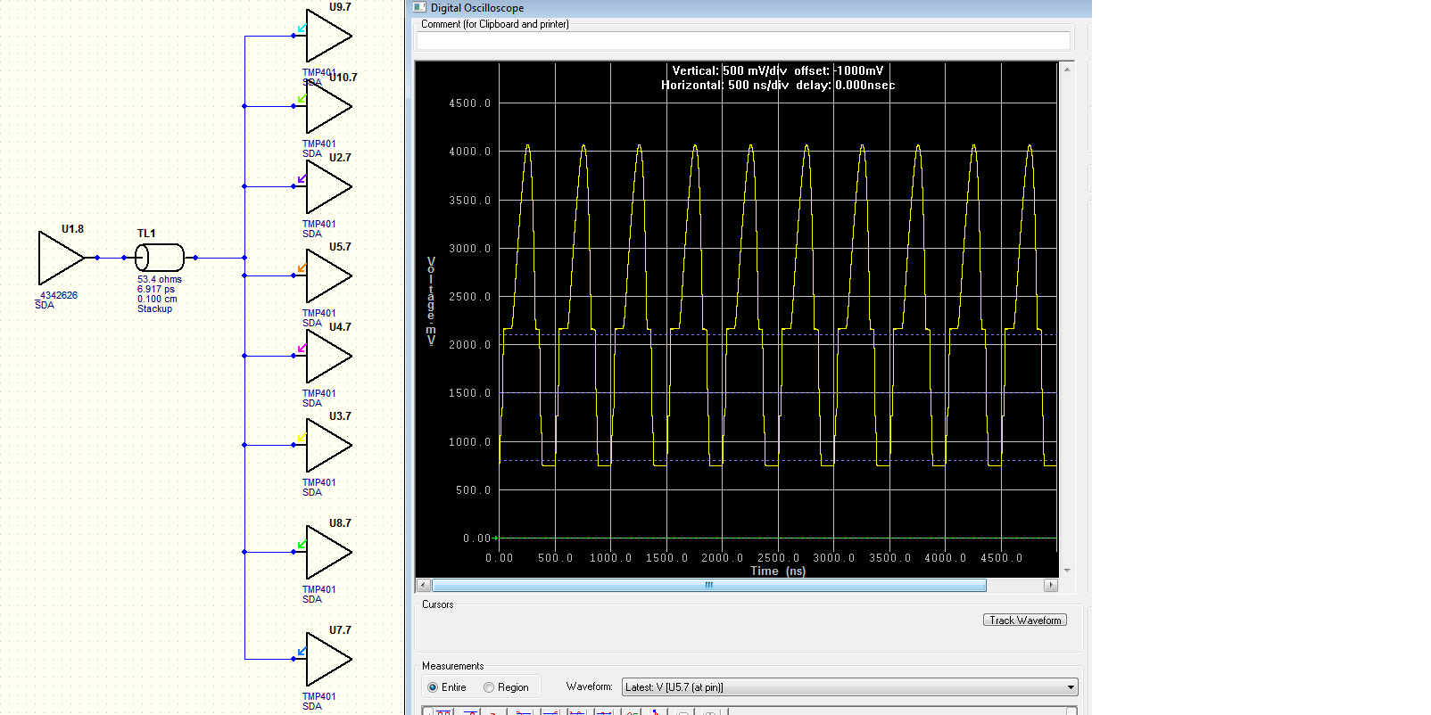
According to the TMP435 datasheet, SDA signal need using  an external  pull-up resistor as it is an open drain buffer.

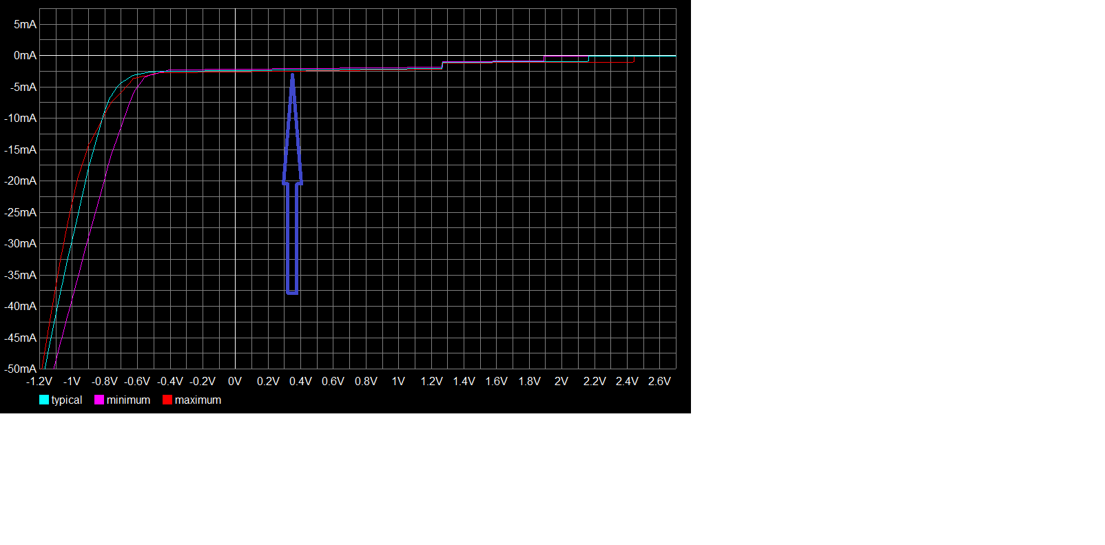
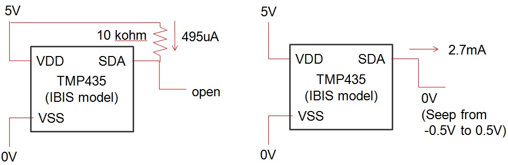
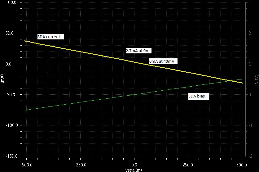
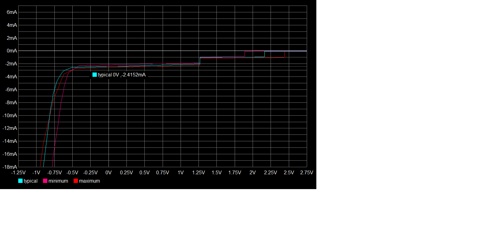
But when I use the ibis model (download from TI website) ,the GND_clamp V/I curve of  SDA_3 model have 2.5mA current in 0V.It just like an internal pull-up resistor exist.

So my question is whether an internal pull-up resistor use in the pin 9(signal SDA)?Is the IBIS model accurate?

TMP435 IBIS
Report Abuse
  • Reply
You have posted to a forum that requires a moderator to approve posts before they are publicly available.
All Replies
  • Chris Featherstone
    Posted by Chris Featherstone
    on Dec 31 2012 12:44 PM
    Expert5125 points

    Shen,

    A pull up resistor is required for SDA and SCL as they are open drains. I will look further into your question about the IBIS model and get back to you shortly.

    Best Regards,

    Chris Featherstone
    Linear Characterization Engineer
    High Performance Linear Products

    Report Abuse
    • Reply
    You have posted to a forum that requires a moderator to approve posts before they are publicly available.
  • Ichiro Itoi
    Posted by Ichiro Itoi
    on Jan 03 2013 16:02 PM
    Prodigy670 points

    Hi Shen,

    Let me update information for your question.

    Actual device does not have internal pull up (SDA pin).

    For IBIS model, it is under survey and get back to you shortly.


    P.S. As SCL(clock) pin is an input pin, it is not an open-drain for this device.

    Best regards,

    Ichiro Itoi 

    Report Abuse
    • Reply
    You have posted to a forum that requires a moderator to approve posts before they are publicly available.
  • Ichiro Itoi
    Posted by Ichiro Itoi
    on Jan 07 2013 16:51 PM
    Prodigy670 points

    Hi Shen,

    This is the update of the IBIS simulation for your question.

    When I sweep the SDA pin with a bias from negative to positive, as shown in the graph, It shows 2.7mA at 0V, 0mA at 40mV.

    I think this replicates your simulation. It would be appreciated if you could send me your simulation schematic and condition. (also include X-axis and Y-axis on your graph. )

    Best regards,

    Ichiro Itoi 

    Report Abuse
    • Reply
    You have posted to a forum that requires a moderator to approve posts before they are publicly available.
  • feiqin shen
    Posted by feiqin shen
    on Jan 07 2013 20:45 PM
    Prodigy60 points

    Hi Ichiro Itoi,

    Thanks for you answer!

    I just do the model checking work. So I haven't the schematic for simulation. 

    Through the Ground Clamp Curve, I can see 2.4mA at 0V.  Could you tell me the origin of the 2.4mA.Leakage current or the pullup resistor current ? 

    If we do the pre-simulation use the Star-topology(One Driver to 8 tmp435).

    2.4mA is  large enough to affect the simulation result.It will increase the bias voltage.You can see in the following picture.

    One TMP435 reciever,

    Eight TMP435 receiver,


    Thank you very much!

    Best regards,

    Shen feiqin


    Report Abuse
    • Reply
    You have posted to a forum that requires a moderator to approve posts before they are publicly available.
  • Ichiro Itoi
    Posted by Ichiro Itoi
    on Jan 10 2013 12:01 PM
    Prodigy670 points

    Hi Shen,

    Thank you for sharing your simulation result.

    If I understand your simulation correctly, the sum of the SDA currents from eight TMP devices raises the low level about 750mV.

    Let me clarify the situation as follows.

    1. Actual device has no pull up circuit internally and there is no current that appears when SDA = 0V (in the condition where no pull up resistor is on the bus).

    2. IBIS model of the device shows SDA = 2.7mA when at  0V  (in the condition where no pull up resistor is on the bus) and it is under investigation.

    3. IBIS model should work with pull up resister on a bus.

    My proposal, at the moment, is to use a pull up resistor in your simulation.

    If there is any reason why there is no pull up resistor on the bus for your simulation or anything I can do, please let me know.

    Best regards,

    Ichiro Itoi

    Report Abuse
    • Reply
    You have posted to a forum that requires a moderator to approve posts before they are publicly available.
  • Ichiro Itoi
    Posted by Ichiro Itoi
    on Jan 11 2013 16:53 PM
    Prodigy670 points

    Hi Shen,

    Could you provide us the simulator name and version, so that I could prepare for the IBIS re-modeling.

    Best regards,

    Ichiro Itoi

    Report Abuse
    • Reply
    You have posted to a forum that requires a moderator to approve posts before they are publicly available.
  • feiqin shen
    Posted by feiqin shen
    on Jan 13 2013 19:31 PM
    Prodigy60 points

    Hi Ichiro Itoi,

    The simulator is Mentor Hyperlynx 8.2.1.

    Thank you!

    Best Regards,

    Shen Feiqin

    Report Abuse
    • Reply
    You have posted to a forum that requires a moderator to approve posts before they are publicly available.
  • Ichiro Itoi
    Posted by Ichiro Itoi
    on Jan 14 2013 21:31 PM
    Prodigy670 points

    Hi Shen,

    Thank you for the information.

    Let me proceed re-do IBIS modeling. I will contact you within two weeks.


    Best regards,

    Ichiro Itoi


    Report Abuse
    • Reply
    You have posted to a forum that requires a moderator to approve posts before they are publicly available.
  • Ichiro Itoi
    Posted by Ichiro Itoi
    on Jan 29 2013 01:01 AM
    Prodigy670 points

    Hi Shen,

     For re-do IBIS modeling, it seems a lot of queues at the moment.

    Let me update status within a week.

     It would be appreciated if you could use pull up resister on your simulation.


    Best regards,

     Ichiro Itoi

    Report Abuse
    • Reply
    You have posted to a forum that requires a moderator to approve posts before they are publicly available.
  • feiqin shen
    Posted by feiqin shen
    on Jan 29 2013 01:22 AM
    Prodigy60 points

    Hi Ichiro Itoi,

    Thanks for the updata.

    I used the pull up resistor in my simulation.

    Best regards,

    Feiqin

    Report Abuse
    • Reply
    You have posted to a forum that requires a moderator to approve posts before they are publicly available.
  • Ichiro Itoi
    Posted by Ichiro Itoi
    on Feb 06 2013 14:55 PM
    Prodigy670 points

    Hi Feiqin,

    It is good to know a pull up resistor is used for the simulation.

    For IBIS modeling, as it is still in the queue, I will update you in a week.


    Best regards,

    Ichiro Itoi

    Report Abuse
    • Reply
    You have posted to a forum that requires a moderator to approve posts before they are publicly available.
  • Ichiro Itoi
    Posted by Ichiro Itoi
    on Feb 14 2013 09:58 AM
    Prodigy670 points

    Hi Feiqin,

    It is still queue for IBIS modeling. I will update you in a week.

     Best regards,

    Ichiro Itoi

    Report Abuse
    • Reply
    You have posted to a forum that requires a moderator to approve posts before they are publicly available.
  • Ichiro Itoi
    Posted by Ichiro Itoi
    on Feb 21 2013 10:13 AM
    Prodigy670 points

    Hi Feiqin,

    The final schedule is not set yet, but most likely it is going to be processed first half of March.

    Best regards,

    Ichiro Itoi

    Report Abuse
    • Reply
    You have posted to a forum that requires a moderator to approve posts before they are publicly available.
  • feiqin shen
    Posted by feiqin shen
    on Feb 21 2013 20:27 PM
    Prodigy60 points

    Hi Ichiro Itoi,

    Thanks for your help!

    Best Regards,

    Shen feiqin

    Report Abuse
    • Reply
    You have posted to a forum that requires a moderator to approve posts before they are publicly available.
  • Eric Kim- WEBENCH Design Center
    Posted by Eric Kim- WEBENCH Design Center
    on Feb 28 2013 10:40 AM
    Verified Answer
    Verified by feiqin shen
    Prodigy430 points

    Hi Ichiro Itoi and Shen Feign,

    Thanks for your patience.

    Attached please find the improved model for the device. The same model will also replace the current one on the web shortly.

    Please let us know how it goes wit the new model.

    Regards,

    -Eric Kim6201.tmp4xx.ibs 

    Report Abuse
    • Reply
    You have posted to a forum that requires a moderator to approve posts before they are publicly available.
12
TI E2E™ Community
  • Support Forums
  • Blogs
  • Videos
  • Groups
  • Site Support & Feedback
  • Settings
TI E2E™ Community Groups
  • TI University Program
  • Make the Switch
  • Microcontroller Projects
  • Motor Drive & Control
Other Communities
  • Deyisupport
  • Designsomething.org
  • beagleboard.org
  • TI on Element 14
  • TI on TechXchangeSM
Other Technical & Support Resources
  • WEBENCH® Design Center
  • Product Information Centers
  • Technical Documents
  • TI Design Network
  • TI Technical Articles
  • TI Training

All content and materials on this site are provided "as is". TI and its respective suppliers and providers of content make no representations about the suitability of these materials for any purpose and disclaim all warranties and conditions with regard to these materials, including but not limited to all implied warranties and conditions of merchantability, fitness for a particular purpose, title and non-infringement of any third party intellectual property right. TI and its respective suppliers and providers of content make no representations about the suitability of these materials for any purpose and disclaim all warranties and conditions with respect to these materials. No license, either express or implied, by estoppel or otherwise, is granted by TI. Use of the information on this site may require a license from a third party, or a license from TI.

Content on this site may contain or be subject to specific guidelines or limitations on use. All postings and use of the content on this site are subject to the Terms of Use of the site; third parties using this content agree to abide by any limitations or guidelines and to comply with the Terms of Use of this site. TI, its suppliers and providers of content reserve the right to make corrections, deletions, modifications, enhancements, improvements and other changes to the content and materials, its products, programs and services at any time or to move or discontinue any content, products, programs, or services without notice.

Follow Us Texas Instruments on Facebook Texas Instruments on Twitter Texas Instruments on LinkedIn Texas Instruments on Google+
TI Worldwide | Contact Us | my.TI Login | Site Map | Corporate Citizenship | mobile m.ti.com (Mobile Version)

TI is a global semiconductor design and manufacturing company. Innovate with 100,000+ analog ICs and
embedded processors, along with software, tools and the industry’s largest sales/support staff.

© Copyright 1995-2013 Texas Instruments Incorporated. All rights reserved.
Trademarks | Privacy Policy | Terms of Use