This thread has been locked.

If you have a related question, please click the "Ask a related question" button in the top right corner. The newly created question will be automatically linked to this question.

ADS7843 PENIRQ no function

Other Parts Discussed in Thread: ADS7843, TEST2, TSC2046

Dear All,

I have facing the /PENIRQ problem. I did tried a lot of testing and changing a few ADS7843 and TFT-touch-screen but still no working.

I would like to compare the result with you all. 

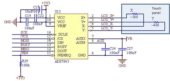
1)  I'm using 3.2" screen. I did measure the touch screen resistance for the X-,X+ is ~300Ohm and Y-,Y+ is ~400Ohm. (without connecting to ADS7843 device)
2) Connect touch screen pin X-,X+,Y-,Y+ to ADS7843 and measure the voltage at point X-,X+,Y-,Y+. (ADS7843 operate at 3.3V and /PENIRQ external pull up 100K Ohm)

No touch on screen:
X+ = 2.315V
Y+ = 2.315V
X- = 0.000V
Y- = 0.000V
/PENIRQ = 3.3V

Touch on screen:
X+ = 2.315V
Y+ = 2.315V
X- = 2.315V
Y- = 2.315V
/PENIRQ = 3.3V

I wonder why the /PENIRQ wouldn't pull to low as per datasheet said once the /PENIRQ is pulled LOW, a voltage typically will not exceeding 0.65V. 

Is it we need to initialize the ADS7843 using coding before we can use the PENIRQ?

Code:
void GetScrXY(int *x, int *y)  
    {
    unsigned char msb, lsb;

// Get X coordinate     
    CS = 0;
    dly(6); 
    
    spi_write(0xD0);
    
    dly(80); // BUSY
    
    msb= spi_write(0x00); // msb
    lsb = spi_write(0x00); // lsb
    
    CS = 1;

    *x = (msb*0x100) | lsb;

    dly(100); 

// Get Y coordinate      
    CS = 0;
    dly(6); 
        
    spi_write(0x90);

    dly(80); // BUSY
    
    msb= spi_write(0x00); // msb
    lsb = spi_write(0x00); // lsb
    
    CS = 1;

    *y = (msb*0x100) | lsb;

    }

void Check_PENIRQ(void)
    {
    int x,y;
    
    GetScrXY(&x, &y) ;

    if(PENIRQ)
        LED = 0;
    else
        LED = 1; 
    }
Above coding is what i trying to use a LED to capture the PENIRQ pin result.

Is there anyone can help me and give some advice?

Thank you,..

  • Hi BC,

    Could it be a connection problem? Please make sure the connection between the touch panel and the ADS7843 is as simple, as short, as secure as possible! Also, may you send me your schematic? Thanks!

    From the info you provided, the touch panel is good, but the voltages at X+/X-/Y+/Y- after the connection seems abnormal.  When you check their status before you run any software and they should be somehow like:

    No touch and no software running either --

    X+ ~= 3.3V

    X- ~= 3.3V

    Y+~= 0V

    Y- ~=0V

    With touch and no software running --

    X+ ~= 3.3V

    X- ~= 0V

    Y+~= 0V

    Y- ~=0V

    The second, you may run software to only enable the /PENIRQ (for example: send a command 0xD0 to ADS7843), then stop the software, and check the X+/X-/Y+/Y- pins status, under no touch or under touch, to make sure they are matching to the above. And the /PENIRQ should reflect the touch or no touch status, i.e.: /PENIRQ high without touch or low with touch.

    If not, it is likely a connection (between the touch panel and the ADS7843) problem, or some hardware problem!

    Regards,
    Wendy F.

  • Hello Wendy,

    Thanks for your reply.

    Above is my circuit connection.

    I through the connection should not be any problem but i have a concern if i connect the ADS pin X+/Y+ to touch panel X-/Y- and pin X-/Y- connect to touch panel X+/Y+ whether it will still working? This should not affect the PENIRQ.

    Ya, i did make the connection as simple as possible and there is no wiring jumper connection, all is PCB connection. I did connect all the pin except the ADS pin-7, pin-8, and pin-12 to pin-16 didn’t connect (without MCU attach) and just make a simple testing on PENIRQ but still not working.

    I did follow your instruction still can’t get the result as you given but the PENIRQ is working in other condition. Please look at the following result:

    TEST1: /CS=1; no command

    No touch and no software running either --

    X+ ~= 2.315V

    X- ~= 0V

    Y+~= 2.315V

    Y- ~= 0V

    PENIRQ = Hi (3.3V)


    With touch and no software running --

    X+ ~= 0V

    X- ~= 0V

    Y+~= 0V

    Y- ~=0V

    PENIRQ = Hi (3.3V)


    TEST2: /CS=0; send a 0xD0 command

    No touch either --

    X+ ~= 2.41V

    X- ~= 0.5V

    Y+~= 2.41V

    Y- ~= 0.5V

    PENIRQ = Hi (3.3V)


    With touch --

    X+ ~= 2.41V

    X- ~= 2.41V

    Y+~= 2.41V

    Y- ~=2.41V

    PENIRQ = Lo (~0.6V)

    The result is very strange. I still further testing it without sending the command 0xD0 just tried to control the /CS pin. Then I found out when the ADS is enable (/CS=0) then only the PENIRQ is function otherwise it will never function.


    Is it something wrong with the ADS?

    I look forward to your reply.

    Best Regards,

    Bc

  • Hi BC,

    The schematic seems no problem at all!

    About your question on the TSC and panel connection: no, it should not have problem with the TSC controller if you swapped the X+ with the X-; or the Y+ with the Y-; or the X+/X- with the Y+/Y-. The affection of the above swapping can only change the coordinate direction (for example, if you swapped Y+ with Y-, you get then the opposited top and bottom Y coordinates) or exchange the X/Y coordinate (for example, if you swapped X+ with Y+ and X- with Y-, you then get the X and Y coordinates exchanged). However, it could be a problem for TSC controller if you mis-paired the X and Y connection, for example:

    ADS7843 pin           Touch panel pinout

           X+                                X+

           X-                                 Y-

           Y+                                Y+

            Y-                                 X-

    Please double check your connections!

    We do not have ADS7843 EVM, but I have a TSC2046 EVM on hand. TSC2046 is a upgrade of ADS7843 (with internal Vref and with added measurements for Z1, Z2 and IC temperature) and thus I captured some X+, X-, Y+, Y- and /PENIRQ waveforms from TSC2046EVM and provide you as reference for your debugging.

    The 4 chs in TEK0000 and TEK0002 are X+, X-, Y+ and Y- respecitively; and the 4 chs in TEK0003 and TEK0004 are X+, X-, Y+ and /PENIRQ respectively.

    The TEK0000 and TEK0003 are that there is no software running; and the TEK0002 and TEK0004 are that the software is running and read X, Y, Z1 and Z2.

    Hope it helps!

    Regards,

    Wendy F.

    TouchXY.zip
  • Hello Wendy,

    Finally the PENIRQ is working. Thanks for your attachment. The waveform and your clear explanation is helping me a lot to find out the problem.

    Ya, you are rite. The mistake was mis-paired the X and Y and cause the PENIRQ not working properly. 

    Thanks you very much.

    Best Regards,

    BC

  • I am so glad the problem was resolved, BC!

    Cheers!