This thread has been locked.

If you have a related question, please click the "Ask a related question" button in the top right corner. The newly created question will be automatically linked to this question.

LM22670 issues

Other Parts Discussed in Thread: LM22670, LM22673

Hello,

We have had some issues with a LM22670 DC/DC design (especially with specific DATECODES) we can't fully explain.

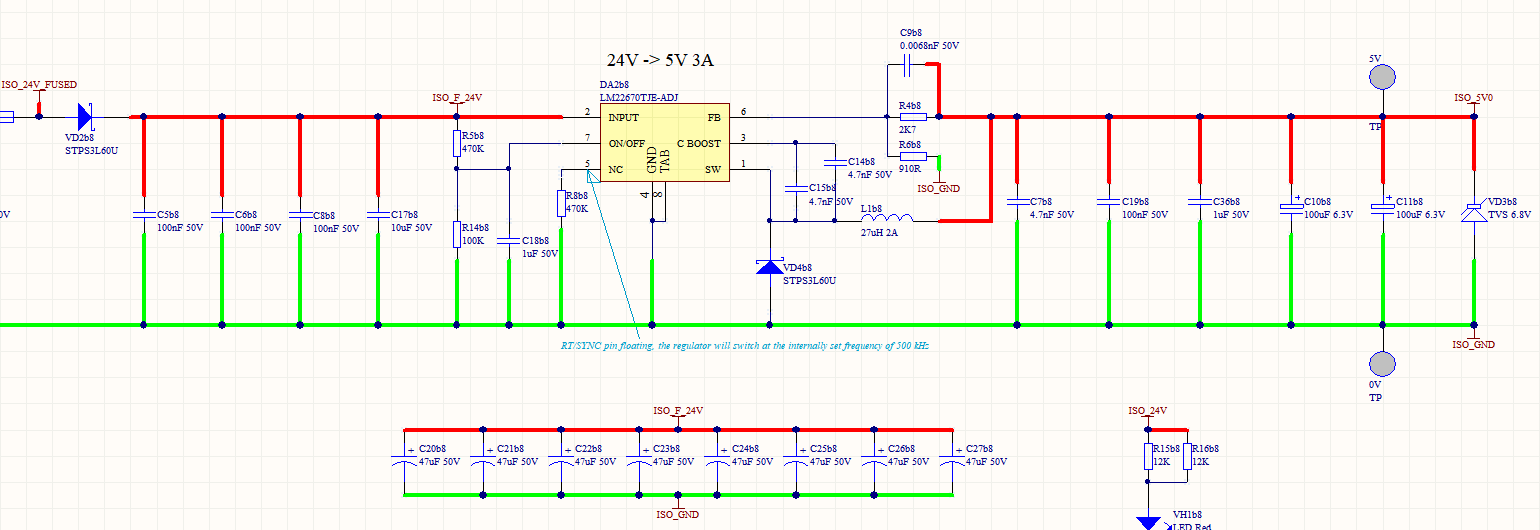
The schematics are the followings :

The input voltage is comprised between 18V and 25,5V, and the output voltage is 3.3V (1.5A)

Our design is stable when simulated with WEBENCH but we saw on our board it is clearly not stable by measuring the current into the output self inductance :

On most of our boards (98%), we do not have any problem, but on several boards, especially with a specific DATCODE (14AB), the LM22670 is damaged (the package burns, pin 7 and 8 are in short circuit...). Can the instability we have found explain this ? There should be overcurrent protection under the conditions described in the datasheet (equation), and our design seems to meet all these conditions. 

An other question : is the LM22670 supposed to be stable with only a few milliamps of output load ? There is no mention of minimum output load in the datasheet.

We couldn't find it in the datasheet the MAX value specified for the TBLK parameter.

We decreased the frequency to 500 kHz, the design is more stable but the component continues to be damaged...

Any idea of what could be the problem ?

Thank you in advance !

  • Regarding the instability shown, is this at the 1.5A or does it appear at other loads?

    There could by several things that cause this.  It could be that the design of output capacitance and ESR are on the

    edge of working with the LM22670 internal compensation.  In that case changes in the internal compensation from

    one part to another could cuase a problems.  You could try to change the output cap value and/or ESR.  A small capacitor

    across the top feedback resistor can sometime help, by adding some leading phase. 

    Another problem might be board layout.

    With a load of a few mA the part should still regulate, however the waveforms will not be constant frequency PWM.

    When you say the part is damaged, I assume you mean when the output is shorted at the maximum Vin ??

    Based on recent testing, for this part, at 500kHz and a short of less than about 0.1V at a Vin of 25V, the part may not survive.  A lower

    frequency than 500kHz may help.

    We do not gaurantee a maximum min-on time; 100 to 200ns might be a good value to use


    Frank D.

    Systems and Applications, TI SVA

  • Please send examples of the complete date codes for a good unit and a bad unit.

    Thank you,

    Allan

  • Examples of complete date codes for a good unit are :

    N 05AC
    L22670
    ADJ

    or

    N 03AD
    L22670
    ADJ

    or

    N 11AB
    L22670
    ADJ


    Complete date code for a bad unit is :

    N 14AB
    L22670
    ADJ

    Thanks,

  • We have measured it with a load of 300 mA, which most of the time is the design output current.

    Changing the output capacitor is what we did first : we tried to replace it with a tantalum one to increase its ESR because we suspected ultra low ESR of the ceramic disrupted the LM22670. Nothing changed.
    We also tried to put a capacitor (with various values) in parallel with the top feedback resistor, it didn't help.

    1- I agree that with a small output load it should work with bursts of pulses, but not with the kind of waveform we currently have.
    A minimum on time of 200 ns would be difficult for our 3.3V output constraint no ?
    Is TBLK the same as On time ?

    When I say the part is damaged I mean that there is a singe on the package at the level of the pin 7, and pin 7 and 8 are shorted (we have Vout = Vin). I assume it is the internal switch that just burned.

    3- I didn't point out, but we suspect that the issue occurs at start up or during shutdown, but not while running (we can't determine this exactly because it is really hard to reproduce).
    The datasheet says that soft-start on the LM22670 is not adjustable and is fixed to 500us. However, is there a way to do a sort of soft-start in order to reduce the current pulse at power on when all the capacitors of the system are empty ? It is an other hypothesis...But we didn't explore it, and anyway in this case we should have this problem on all our boards no ? not only on few percent of them, and why with a specific DATECODE. There must be part related instability, maybe aggravated during start up or shutdown phase.

  • Looking at your waveform, it may be that you are running into a minimum on-time limitation.  This will vary from part to part.

    I would try slowing down the switching frequency and see if the un-stability goes away.

    The "blow-up" problem may also be related.  Based on our experience, even 500kHz is too fast for the part to survive a short at

    Vin=25v, or a prolonged start-up.  Try 300kHz.

    Frank D


  • You can also use the LM22673 which has an external Softstart function.

    We checked the datecodes and there is nothing that stands out about fab site or manufacture date. Basically this tells me that you are seeing typical part to part variations in minimum on time.

    Regards,

    Allan

  • Hello All

    We are having a similar issue to this older thread although the occurrence of the LM22670-ADJ failing is less than 1% and extremely random. BTW does this need to be a new post?

    Our Production is currently running at over 2k pcs per annum for the design shown below, resulting in a dozen or more systems being scrapped.

    Note the RT resistor is not fitted in the design below.

    All products using this PSU design are tested by the PCB board loader so arrive at our factory fully operational.

    When some products are bench powered or soak tested (8 hours) the LM22670 dies on power up, usually 20R between Vin and SW and 0R between SW and 0V.

    As was mentioned previously in this thread, we also surmise that the internal FET has failed in some manner and the output protection (steering diodes??) have also failed.

    Using an approximation of our design in Webench there looks to be an issue with the output voltage - someone may be able to point out the error in my Webench design here:

    webench.ti.com/.../SDP.cgi

    Lastly this PSU experiences very light loads for several seconds (less than 100mA) before the system controlling this board powers up. The bulk capacitance on the input side of the switch mode is to ensure that this board meets EN 61946 - 1 : 4.3.2.2 Supply voltage interruptions.

    Any suggestions or comments regarding this issue are welcomed.

    Regards

    Greg

  • It is a little hard to read what input cap you have.

    Are the Al. electrolytic?

    It looks like some overvoltage on the input cuasign the damage.

  • Hi Frank

    The output has 2 ceramics and 2 polymer electro's (49mR with a 1.8A ripple at 100kHz)

    UMK107BJ105KA-T

    GRM188R71H103KA01D

    2 x 6SVP100M

    The input is clamped with a 33V Transorb, however the max breakdown of a SMCJ33CA can be 53V and this is more intended for EMC compliance.

    During all tests these units are powered from benchtop power supplies set at 24V. Additionally different power supplies from different manufacturers result in the same sporadic failure of the TI device.

    Was there a reason you were considering overvoltage, as opposed to very light loads on the output, as the possible cause of failure? If overvoltage is one of your concerns, what type of voltage comes to mind? We can soak test units for several hours through continuous power cycling with higher input voltages >30VDC if this is a concern?

    Regards

    Greg

  • Most of the time when the package is damaged it is from over voltage.

    It could be some kind of spike on the input supply or a resonance with the wiring from the input supply.

    You may want to send the damaged unit back to TI for analysis.

  • Thanks Frank, we will raise an RMA, appreciate the support.