This thread has been locked.

If you have a related question, please click the "Ask a related question" button in the top right corner. The newly created question will be automatically linked to this question.

tlc5940 with higher current LEDs

Other Parts Discussed in Thread: TLC5940, TPS61500, TLC5960

Can the tlc5940 be used with much higher current LEDs of about 700mA say with an external FET? If not does TI have another 5940 type device that has a current sink capability of 700mA?

  • This app note is applicable to the TLC5940 also: http://focus.ti.com/lit/an/slva253/slva253.pdf

    We also have high current LED drivers in a boost topology, such as the TPS61500.

  • Thank you Chris. I guess I will try the parelleling technique if nothing else is available. Unfortunately, the tps61500 type devices will not work because I am driving several LEDs and I need multiple channel outputs.

  • Ok, I am using the application note suggested above to use the 5940 with 700mA LEDs by ganging up 6 outputs per LED. I am using a 330ohm resistor to set Imax to about 120mA. The power dissipation of the PDIP I am using is rated about 2.45w at 25deg. Celcius. I am not sure on what values to use for Icc and Vout in the PD equation in page 15 of the data sheet. I basically want to make sure that the device will be safe in all operating conditions between 0 ~ 100% duty cycle PWM control. On tests I have done so far, the  5940 devices(daisy chained) get between warm and hot during use. Should I be concerned about damage?

  • Icc is the IC's supply current as specified on page 4 of the datasheet.  There are various specs for various operating conditions, so use the spec that matches what you are using in your system.

    Vout is the voltage at the OUT pin (LED cathode).  This voltage multiplied by the current being sunk (700mA) is how much power is lost across the internal drive transistors of the TLC5940.  You can measure this voltage on your board or calculate it based on the forward voltage of your LED at 700mA.  To reduce the power lost in the TLC5940 (and reduce its temperature), you can reduce the voltage on this pin by using a lower voltage for the LED anode.  We have many buck converters or LDOs that will do this for you.  See figure 5 for the minimum Vout headroom required.  For 120mA, it is about 1.2V.

    Yes, as long as the maximum junction temperature rating is not exceeded (maximum power dissipation spec at 25 C), the IC will operate fine.  But it will be hot!  Note that the maximum power dissipation rating assumes a JEDEC board.  Junction temperature is a function of the actual theta JA on your board, power dissipation, and ambient temperature.

  • I have the same question as the original post in this thread. In my application, I need PWM control of 64 different LED strips, which require 12V and draw ~400mA. If at all possible, I would prefer to use only 4 TLC5940, with 1 output channel per LED strip, rather than having to use 6 outputs in parallel as noted in slva 253 - LED Driver--Paralleled Outputs Provide High Current Outputs. Is there some way to use an FET as a current switch?

  • Michael,

    You might have a look at the TLC5960 (8-channel) driver.  It is designed for use with external FETs.  It was intended for backlighting applications, but can be used in other high current / multi-channel apps as well.  Unlike most of the other TLC series LED drivers, this one does not have a SPI or I2C port.  String dimming is done using the PWM input pins.

    Hope this helps.

    John

  • Thank you John for the quick response.

    First off, let me say that I completed an undergrad Electrical Engineering (EE) degree over 30 years ago, then went into IT, so my EE skills are quite rusty.

    I am trying to work with someone else's existing design, where they are driving 64 individual RGB common cathode LED's, using an Arduino board (ATMEGA microprocessor) to multiplex power (via simple transistor) to the R or G or B anodes and to control 4 TLC5940s to PWM the current sink on the LED cathodes.

    If at all possible, I would like to make use of their design including use of the TLC5940's. Is there anything you could suggest for a circuit that would take the PWM'd constant current sink of the 5940 outputs and use that to switch ~500mA of current sink for my LED strips. The strips themselves have integrated resistors, so controlling their current is not an issue.

    Michael

  • Michael,

    Looks like there a lot of folks using this processor for LED projects.  I saw a number of posts similar to yours on the Arduino forum (http://www.arduino.cc/cgi-bin/yabb2/YaBB.pl?num=1238693450/30).

    The TLC5940 was designed primarily for LED display (think jumbotron) applications.  When used for this purpose, the LED current regulation accuracy is important and is therefore sensed/controlled inside the IC.  This is how we are able to achieve good current matching between the channels on the driver.

    Having said all of this, the TLC5940 and other TLC59xx drivers get used in a lot of creative, non-signage applications, hence the app notes for paralleling channels or using external FETs for higher voltage strings.

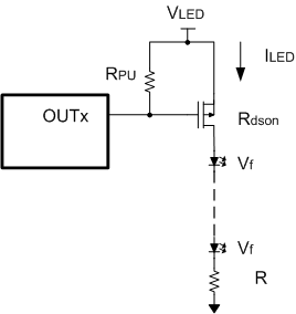
     If it is not possible to significantly redesign the circuit, then you could do something like this.  The LED current would then be given by below and is no longer internally regulated by the TLC5940.

    ILED = (VLED - n x Vf) / (R + Rdson)

    where:

    • VLED = supply voltage for LED strings
    • Vf = forward voltage of the LEDs (note these vary by color and within a particular color)
    • n = number of LEDs in series

    Since the LED forward voltages vary slightly and change with temperature, you may notice some brightness differences between strings especially at deeper dimming levels.

    Hope this helps.

    John

  • Thank you John. This is quite helpful.

    I have some logic level p-channel mosfet transistors I can use to test this. The led strips I am using have integral current regulating resistors, so I don't think I need resistor R in your diagram. I realized that Rdson will cause a bit of a voltage/current drop.

    If Vled is 12V, do you have recommendations for the target current for the TLC5940, and for Rpu? I am guessing that will be determined by the characteristics of the mosfet, which I do not have handy at present. If I post the mosfet characteristics, can you help with sizing the target Out current and Rpu?

    I really appreciate you taking the time to help with this.

    Michael

  • Michael,

    It is probably going to take some iterations to get the performance you want.  Before you start, be sure to check the ratings of the logic PFET to make sure it can handle the current you are going to put through it.

    You can start with 1k for Rpu.  The LED turn off will be slow, but it won't waste a lot of power.  You can decrease it incrementally until you get the results you want or become limited by what the TLC5940 can sink and turn the FET on.  For LED turn on, you'll need to play with the current set resistor on the TLC5940 to make sure you have enough current to pull the gate low with the Rpu you have chosen.

    John

  • Good morning John,

    I am expecting delivery of some sample TLC5940 for testing within a few days. I already have some of these logic level p-channel mosfets on hand: http://www.fairchildsemi.com/ds/ND/NDP6020P.pdf. These appear to have a current rating of 24A, and fast switching as well as low on state resistance for minimal power loss.

    Here's my understanding of how your recommended circuit would work:

    For LED turn on, the TLC5940 output will sink current at a level determined by the current set resistor. This current will determine the voltage drop (Vpu) across the pull up resistor (Rpu), and thus the mosfet gate voltage will be Vled- Vpu. For my logic level mosfet, this gate voltage needs to be fairly close to zero.

    For LED turn off, the TLC5940 output will present a high impedence, and the mosfet gate will be pulled up to Vled through Rpu (do I have this right?), so this happens faster the smaller Rpu, correct?

    So let's say I want to drop all 12V of my Vled across Rpu for LED on. Thus the output current sink (set by my current set resistor) * Rpu needs to be ~12, right? So my theoretical limit, assuming the limit of the TLC5940 is ~120mA/per output, would be to use Rpu =100 ohms. And for your recommended starting point, Rpu=1k implies current for the TLC5940 set to 12mA.

    Do I have this right, and would it make sense to iterate from Rpu at 1k towards Rpu of 100, adjusting the current set resistor accordingly?

    Thank yo so very much for all your help with this?

    Michael 

  • Michael,

    For LED turn on, the TLC5940 output will sink current at a level determined by the current set resistor. This current will determine the voltage drop (Vpu) across the pull up resistor (Rpu), and thus the mosfet gate voltage will be Vled- Vpu. For my logic level mosfet, this gate voltage needs to be fairly close to zero.

    Yes.

    For LED turn off, the TLC5940 output will present a high impedence, and the mosfet gate will be pulled up to Vled through Rpu (do I have this right?), so this happens faster the smaller Rpu, correct?

    Correct.

    So let's say I want to drop all 12V of my Vled across Rpu for LED on. Thus the output current sink (set by my current set resistor) * Rpu needs to be ~12, right? So my theoretical limit, assuming the limit of the TLC5940 is ~120mA/per output, would be to use Rpu =100 ohms. And for your recommended starting point, Rpu=1k implies current for the TLC5940 set to 12mA.

    Do I have this right, and would it make sense to iterate from Rpu at 1k towards Rpu of 100, adjusting the current set resistor accordingly?

    Right.  For simplicity, you might start by setting the TLC5940 to sink maximum current (330 ohms) with the 1k Rpu and then work down as needed towards 100 ohms.  You want to keep Rpu as high as possible so you don't waste power in the driver outputs unnecessarily.  Page 10 of the datasheet has I-V curves for the outputs which will be useful in dialing in the optimal setting once Rpu is fixed.

    John


  • OK John, you have been most helpful, and I think I have all the information I need/can use while I await arrival of my TLC5940s. I will report back with results once I have my test circuit set up... Once again, thank you for your time and patience in explaining this to me.

    Michael

  • Hi John (if you are still monitoring this thread),

    I have received my sample TLC5940 chips and have begun basic testing, and it occurs to me to ask a basic (and perhaps stupid!) question. In the basic circuit you suggested, do I simply connect the TLC5940 ground, my LED strip cathode, and my power supply (400 watts at 12V) ground together. The 5940 is powered & grounded with a USB port on a PC through an Arduino project board. What keeps the high current flowing through my LED strips from my Arduino/USB/PC and drains it through my power supply?

    Michael

  • Hi Michael,

    As I understand from John's circuit; the led string cathode is anyways not connected to the ground (but to the resistor R).

    However, your question still stands. What is usually done is we keep all the power grounds together in a bunch and all the signal grounds in another bunch : then we connect them together at 1 point in the circuit with a small, short connection. (Pardon my crude use of english here)

    Hope it helps if John is not here to elaborate further!

    Regards,

    Rohan.

  • Thank you Rohan.

    I am using 12V LED strips, which have resistors built in. These resistors limit the current to each LED, but as I am using a large number of long LED strips, the total current will be significantly higher than what my computer's USB port can handle. If I understood you correctly, it is OK to connect my tlc5940 ground, my arduino ground, and my 12V 400W power supply ground together. Is that right?

    Michael

  • Hello Michael,

    Yes, you are using a single GND connection and please keep it as low impedance as possible. The current coming out of the power supply will as well flow back to the power supply because current is always flowing in circles. There is no possibility that the current coming out of the power supply is going into your USB power source.

    If you have good ground connections (lowest possible impedance) the system will work.

    Best regards,
    Brigitte

  • Brigitte is absolutely correct.

    My suggestion basically tries to keep the high current paths away from the low current ones to get a better performance.

    Regards

    Rohan

  • Hi John! I have build an 80 channel (5 TLC5940 daisy chained), p channel Mosfet power driver, using the IRF9540 mosfets. Everything seem´s to be ok, no TLC heated until last less than a minute, one began to heat like grilling bacon. In total, the last 3 in the daisy chain died. I look for troubles in the circuit board, connections, etc, but found nothing. Every single plate works good alone, but after swapping the order of the boards, and changing the dead TLC´s, one more time, the last 2 bourned out in 30 secs. As I looked in the internet, I found people, who have the same problem:

    http://forum.allaboutcircuits.com/showthread.php?t=66777

    http://forum.allaboutcircuits.com/showthread.php?t=74419


    My RPU´s are 1K, I add to every Output of the TLC a single, low current Led with his own 1k limiting resistance, to check the out state. (The resistor let me try different output currents)

    This led goes to Vled, who is 12V

    Do you have any idea what is happening? Should I use an logic inverter and ULN2804 on the outputs, to isolate the TLC´s from the Mosfets?

     Any help will be welcome.

    Sorry for my poor english, and thanks in advance.

    Ricardo Bordenave

  • Hello Ricardo-san,

    Could you please conform for below two things? 

    1. Could you please confirm the sequence between Vcc and input signal?


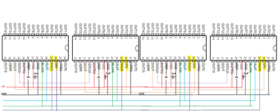
  • Hi Kiyoshi-san: sorry for the late answer. I was on hollyday. what do you really mean with your question? All the TLC`s are 5V (regulated) powered, grounded all together with an 1mm in diameter cable with the arduino (to prevent any gnd shifting) . Near each chip I put an .1 and a 10uf capacitors. No one get hot, until suddenly they burn out. Here is an basic schematic on how i Daisy chained the TLC`s .

    Thank you for any suggestions. 

    Ricardo