This thread has been locked.

If you have a related question, please click the "Ask a related question" button in the top right corner. The newly created question will be automatically linked to this question.

UCC28180: UCC28180 PFC : distorsion of the PFC coil current

Part Number: UCC28180
Other Parts Discussed in Thread: TIDA-00443

Hello

Please could you give me some explanation (application note or something like that) on how the Vcomp and Icomp are generated inside UCC28180. This is for my personnal understanding :-). In the datasheet, the voltage error amplifier transconductance gain is specified -56µS, that is to say that if V sense is lower than 5V internal regerence, the voltage error output will decrease ???? so Vcomp will decrease and this is not logical... Please could you explain me how it works

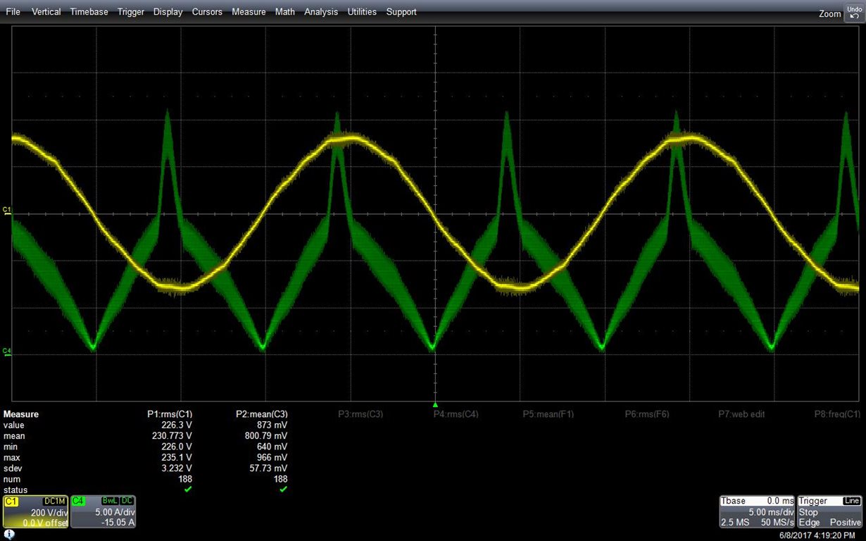
I have designed a 2.5 kW PFC for 230Vac mains following the SLUC506revA design calculator. The PFC is fine till 2kW.  and from that point I got a big distorsion on the PFC coil current

Yellow is input voltage and Green is PFC coil current for 2.5kW out.

The coil inductance is 200µH for 15A, and is not saturating and variations of compensation components on Vcomp and Icomp had not effect.

In order to solve the problem, I had to reduce Rsense from 0.01 Ohm to 0.006 Ohm and I got a correct shape for inductor current.

Why did I get the wrong shape when Rsense is 0.01 Ohm (although it correspond to the design calculator)

Thank you for your help

Didier

  • Hello Didier

    this is a known issue and one of my colleagues describes the cause of this problem as follows -

    'This abnormal waveform is because the value of Rsense too high, which causes ICOMP reaches its upper limit and be clamped there, then the current loop becomes an open loop, a fixed PWM duty is generated at AC peak, which causes AC current spike. Reducing Rsense is the only way I can suggest.


    UCC28180 is designed for the universal input range 85VAC~264VAC, if the current sensing resistor is not calculated with 85VAC, you may see this behavior.'

    I hope this helps

    Regards

    Colin

  • Hello Colin

    Happy to know that it is a known issue.

    What is the upper limit on Icomp pin ?

    Please could you give me some explanation (application note or something like that) on how the Vcomp and Icomp are generated inside UCC28180

    Do you have an application schematic in order to limit maximum possible current externally (with 0,006 Ohm for Rsense, SOC protection will be 48A that is more than 3 times the designed power !) or do I have to conclude that in the range of 180Vac-230Vac the current protection is not really applicable with this controller ?

    thank you

    Didier

  • Hi Didier

    I don't think that the current limit would be 3 times nominal current. Please have a look at the reference design at www.ti.com/lit/ug/tidu962b/tidu962b.pdf  . this is a 230V (nominal) input voltage design and the current limit is set at 125% of full current. The current is fully sinusoidal at full load but shows some peaking at the over current point (Figure 26 on P38). This peaking could be reduced by setting the current limit point a little higher and using a slightly lower value of current limiting resistor. Please look through the calculations for the ICOMP compensation in section 4.2.13 (P15) - these actually mirror the example in the datasheet but the main point is that you can control the current limit point.

    The upper limit of ICOMP is about 6V.

    I don't really have a better explanation of how VCOMP and ICOMP are generated internally than that given in the datasheet - sorry. Do remember that this controller is a leading edge modulated type so increases in the voltage at ICOMP command a smaller duty cycle - not a larger one - Figure 28 in the datasheet illustrates this.

    There are a few other posts in e2e discussing this topic - you may find this one here useful

    https://e2e.ti.com/support/power_management/isolated_controllers/int-isolated_controllers__motor_controllers/f/190/p/515206/1880621?tisearch=e2e-sitesearch&keymatch=bosheng%20sun#1880621

    Hope this helps

    Regards

    Colin

  • Hello Colin

    Thank you for the answer

    I ve read the explanations on reference design., but it seems that this reference design has the same problem : for 230Vac, 900Wout, the input current is nice . But if you calculate the voltage on Icomp, you find that Icomp is just at the limit of saturation (6V). When the device is tested with overcurrent, you find again the peaking on the current curve (fig26 on page 30 ofTIDU962B, and this is due to saturation of the Icomp amplifier... So the only way to deal with this problem is to decrease the switching frequency (but in that case you need to increase the coil in order to prevent higher current ripple and risk of saturation) or to decrease the sensing resistor (but in that case the SOC will not be very accurate). Moreover, as input voltage decreases, Icomp saturation level is reached for a lower output power. So it seems that the SOC is ok for nominal input value, but this protection current level will vary greaty with input voltage.

    Please, could you explain me what is the non linear gain variable M3 ? In both datasheet and Tidu962B, there is a calculation on this parameter, but they don't explain what it is used for.

    Concerning the post :
    e2e.ti.com/.../1880621

    it seems that there is an access problem. Below is the message I get when I try to access to the post :
    "Access Denied (Note: a common reason this message is displayed is because the thread was deleted)
    You do not have permission to view/download this item."

    Is this post still valid ?

    Thank you

    Didier
  • Hi DIdier

    Yes - the thread is still active - I followed the link just now and it worked.

    Please let me think about this some more- it may be a day or two before I get to post a reply - you are correct that the TIDA-00443 has the same issue.

    Regards
    Colin
  • Hello Colin
    Any new ?
    I was not able to connect to the post
    e2e.ti.com/.../1880621
    Seems I have no permission to view this item ?
    Is there any other way to access to this post ?
    Thank you
    Have a nice week end
    Didier
  • Hi Didier

    Strange.... - here is a .pdf  version of the item.

    /cfs-file/__key/communityserver-discussions-components-files/196/7024.DC-Power-_2800_Read_2D00_Only_2900_-_2D00_-TI-E2E-Community.pdf

    If that doesn't work then please email me at colingillmor@ti.com and I'll send the file directly to you.

    Enjoy your weekend.

    Colin

  • Hello Colin

    Thank you for the pdf version. it confirms that the only way to increase power is to decrease the sense resistor.

    Please, could you provide me more explanations on current amplifier gain (how is it calculated inside the UCC28180) and the purpose of M3 parameter

    Regards

    Didier