This thread has been locked.

If you have a related question, please click the "Ask a related question" button in the top right corner. The newly created question will be automatically linked to this question.

TPS92310: Ripple output at the output..

Part Number: TPS92310
Other Parts Discussed in Thread: LM3424

Hi,

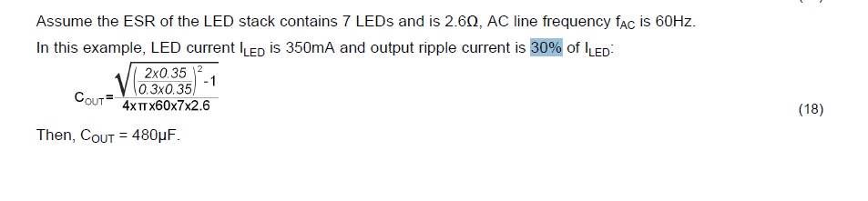
Please find the attached Isolated 7Watts CC circuit. I have a problem at output voltage which is having 3Volts of ripple out put. Tried increasing the Cout(to 470Uf + 220Uf) but still ripple(50Hz , 3Vpp) been seen. 

Rgds

ChandraACTODC_CONV.pdf

  • Hello Chandra,

    This is a Power Factor Corrected circuit so I assume you are seeing 100 Hz or 120 Hz ripple depending on your source frequency (not 50 Hz)? If you are seeing 50 Hz something else is incorrect. If this is a constant current application you should be looking at the LED current. Voltage ripple will exist unless Cout is very large. Adding 220 uF to 470 uF should make some different (enough to see) but not much since it is only a 46% increase). To be zero ripple Cout would have to be infinite.

    The current from a power factor corrected controller is trying to regulate the input current to look like the input voltage which causes the output to see 100/120 Hz ripple for 50/60 Hz sources.

    Do you have the specification for the LEDs being used specifically the Vf versus current curve (this gives the dynamic impedance of the LED stack)? Is the output around 24V like the schematic shows meaning about 300 mA of current in the LED string?

    This is assuming the circuit is operating correct. If the circuit is operating incorrect there are other issues.

    I=C*dv/dt shows it possible to have that much ripple with 470 uF. But I restate this, you should be more concerned with current ripple. You need to be able to measure the current in the LED stack to see if it is operating as it should.

    Regards,
  • Hi,

    The Led been used is "MLCAWT-A1-0000-000XE5" , we have total of 21 LEDs been connected in 7 series and 3 parellel string combination.

    Due to ripple voltage(apx 5Vpp) at output we see flicker at LEDs. Also from the datasheet in page 17 not sure what is 30% of ripple talking about, if it is 30% then how about the flicker.

    Rgds

    Chandra

  • Hello Chandra,

    The datasheet for that LED shows it as being a two die LED, are you connecting these in series or parallel?  Are you using both die as one LED or each die as the LED in your design?  What is your output current to the LEDs?  To calculate the dynamic impedance I need to know how the LEDs are configured for the output and the output current as well as if you are using both LED dies as one or individually.  Or an easier question, are you using 11 MLCAWT LEDs or 21?

    For example I calculated the LEDs operating near the maximum specification:

    If one die of the LED is used as a single LED in your 7 series, 3 parallel configuration the output current at maximum for the LED specification would be 525 mA and the dynamic resistance would be about 9.3 ohms.  This would use 11 of the MLCAWT led packages with one LED die not being used (11 LEDs X 2 die = 22 die minus one to get to 21 die)

    If both die of the LED is used as a single LED in you 7 series, 3 parallel configuration the output current at maximum for the LED specification would be 1050 mA and the dynamic resistance would be about 4.7 ohms.  This would use 21 of the MLCAWT led packages.

    The equation is for setting the LED current ripple to 30% of the average output current (the calculated DC output level).  This number can be changed to fit your design, if you reduce the ripple percentage the output capacitor will get larger.  What are you expecting for LED ripple percent?

    It would be helpful if you could measure the LED current with an oscilloscope.  It would also be helpful to know if the TPS92310 is operating correct.

    Regards,

  • Hi,

    Sorry for the confusion created, I have 7 LEDs in series, as below. 

    Rgds

    Chandra

  • Hello Chandra,

    What is your output current? I cannot calculate the dynamic resistance without that. Also, are there two 50 ohm resistors in series with the LEDs? (50R means 50 ohms). This is also part of the resistance to calculate output capacitor value.

    Regards,
  • Dear Irwin,

    Yes 50R means 50 ohm resistor. They are current limiting resistors. Our goal is to have 200mA current.

    Rgds

    Chandra

  • Hello Chandra,

    Each 50 ohm resistor at 200 mA will have a 10 volt drop across it.  Two 50 ohm resistors will have a total of 20 volts drop, they will also need to be rated for at least 2.0 watts of power dissipation.

    The LED string of seven dual die LEDs will have a total voltage across the LEDs of 24.5 volts.  Add the 20 volts from the resistors the total string voltage will be 44.5 volts.

    The dynamic impedance of the string not including the resistors will be approximately 18.2 ohms, with the resistors it will be 118.2 ohms.  A 470 uF capacitor across this should have very little current ripple so something else must be happening if you visually see flicker.  I assume the output capacitor is tied across all of the LEDs and the two resistors? 

    Also, if 200 mA is run through the seven LEDs and two resistors the efficiency of the string only (not including the power supply) will be 55%, 45% of the power is being lost in the two 50 ohm resistors.

    Perhaps the added voltage drop from the resistors is causing OVP protection to kick in (44.5 volts)?

    The TPS92310 should be able to regulated the current in the LED string without the 50 ohm resistors.

    Using the Cout equation without the 50 ohm resistors the output capacitor for 30% ripple would be 413 uF, with the two 50 ohm resistors 64 uF.

    Regards,

  • Hi Irvin,

    Last week I was not able to spend time on this issue.

    We checked with current probes current is switching. I have more hints, When we probe across output diode we see transformer output switches on and switches off may be due to it see over voltage or VZCD,

    Below is the waveform,

    Most importantly, we do not have any snubber circuit, does it play any role. In TI EVM it is suggested as optional(C2 and R3) we are not sure why 

    In additional to above board is tested with 7 LEDs in series

    Rgds

    Chandra

  • Hello Chandra,

    Yes, that's not operating correct. Can you look at VCC going to the IC or the voltage at C125? Also can you look at the ZCD pin, it will be getting close to OVP threshold when the output is at 27V. I also don't understand why the output is getting to 26.8V if you have seven three volt LEDs unless the current is much too high. I recently found out that your resistors are not 50 ohm but are 1 ohm, is this true? If the 50 ohm resistors are still there that will be a problem, they should be shorted or reduced to a low value that doesn't cause a large voltage drop.

    The snubber/clamp is there to clamp the leakage energy of the transformer when the MOSFET turns off. Your design is fairly low power so it may work without it depending how the transformer was manufactured. You can look at the drain waveform to see how high it is going. If it goes high enough either the MOSFET will avalanche or one of the rectifier diodes (secondary side or primary bias winding) will avalanche. It's possible there's enough parasitic capacitance that it won't. Also, the snubber/clamp circuit can reduce EMI.

    Are you using transformer 750341087 with 7.615:1 ratio?

    Regards,
  • Hi Irwin

    if you have seven three volt LEDs unless the current is much too high. I recently found out that your resistors are not 50 ohm but are 1 ohm, is this true? If the 50 ohm resistors are still there that will be a problem, they should be shorted or reduced to a low value that doesn't cause a large voltage drop. -- yes it is shorted.

    Are you using transformer 750341087 with 7.615:1 ratio? --> yes we are using same.


    Below is one more waveform together with Output voltage and transformer output,

    Rgds

    Chandra

  • Hi Irwin,

    Attached the xls with calculation for our design, one more observation is from xls we get,

    ZCD pin resistor R10(In our case R65) 643 kΩ(In EVM and our case 66.5K)

    ZCD pin resistor R12(In our case R58) 13 kΩ(In EVM and our case 11K)

    TP9S92310_Calculation_tools__REV1 3a.zip

    Rgds

    Chandra

  • Hi Irwin,

    In one of the board we changed the value of R65 to 499 and R58 to 30K and added RCD snubber(R=SMF3W150KJ, C=1812B102K202CT, D=1N0007), now we are able to see constant voltage and no hiccup of OVP , also we see expected current output for 7 series LEDs.

    But now big problem started, We see U15(TPS92310DGS), R55(3 ohm resistor), Q1(STD3NK80ZT4) getting damaged in some of the boards even with the some of working boards also. We are sure rework is good.

    PS: we observer this type of behavior(U15, R55, Q1 getting damaged) even without snubber circuit when we removed R50(Current limiter) and added 0.5 Amps fuse in that place. We removed R50 and tried with fuse because this resistor was frequently getting damaged.

    Rgds

    Chandra

  • Hi Chandra,

    The ZCD resistors will not work with the new values you have, 499 ohm and 30 Kohm set the ZCD at 0.36V using a 22 volt output. the transformer you are using has the same turns ratio for the secondary and primary bias so the primary bias will be close to the output voltage. Also, what are your resistor values in series with the LEDs, I saw 50 ohms and someone stated they were changed to 1 ohm? If they are still 50 ohms the primary bias voltage will get too high and possibly damage the LM3424 (I would expect R57 to open before that). Can you measure the output voltage?

    The diode you chose for the snubber needs to be much faster response than the 1N4007. A 1N4007 is a rectifier diode for 50 or 60 Hz. The snubber clamping frequency is above 50 KHz. It's good you chose a 1000V diode but its recovery will be too slow.

    Also, a 30 Kohm will see Vout times transformer 'n' which is 7.615. If Vout plus Vfd = 22V, Vreflected will be 167V across the 30K resistor which is almost one watt (this depends on what Vout really is). You could replace the snubber R with a 200-350V transient supressor and the diode with a 1000V ultrafast recovery which would work (again depending on what Vout really is).

    Regards,
  • Hi Irwin,

    Sorry it is 499K Ohm typo error.

    what are your resistor values in series with the LEDs, I saw 50 ohms and someone stated they were changed to 1 ohm? --> I already mentioned that 50 Ohm is replaced with Short.

    Also, We expect the Vout of 23V to 24V becuase 7*3.2V(LED VF) = 22.4 V

    Rgds
    Chandra

  • Hi Chandra,

    499 Kohm and 30 Kohm is too close to having issues as well. The ZCD arming threshold is 1.24V (max spec at 1.3V), at 22.4V this voltage from the divider will be 1.27V. There may be issues with part tolerances or thermals as the LED stack voltage will drop with temperature.

    22.4V * 30K/30K+499K) = 1.27V, this is because the primary bias and secondary winding are the same turns ratio.

    Regards,
  • Hi Irwin,

    Looks like we nailed down to the issue we had it. 

    1. Wrong calculation of two resistor of Vzcd, Proper values are between 63K~73K and 11K. Attached the sheet for our circuit.

    TP9S92310_Calculation_tools__REV1 3a_chandra.zip

    2. Missing snubber circuit also related to this high current and voltage spikes in primary side. Which is said optional in EVM.

    3. Mosfet miss leaded because chosen FET is not good compared to the one in EVM for SOA. Mosfet SOA and Miller region we need to validate with our circuit and layout. Also found mosfet we are using is not same as been used in EVM, Coss is almost 10 times more in our mosfet, Below is the SOA, for our mosfet not sure about the Id at SOA region for our mosfet because we are at 75Khz switching frequency.

    4. Layout improvements required to increase thickness of traces in certain area.

    Rgds 

    Chandra