This thread has been locked.

If you have a related question, please click the "Ask a related question" button in the top right corner. The newly created question will be automatically linked to this question.

BQ24600: Battery Detection Issue

Part Number: BQ24600
Other Parts Discussed in Thread: CSD16404Q5A

Hi,

BQ24600 IC is been used in the charging circuit for one of our application.

I've been facing an issue of battery charging!! The pack is not getting charged!

The circuit is designed for 4 cells in parallel lithium-ion pack with charge current of 4A.

The circuit is exactly same as the EVM with change of the part for MOSFETs (instead of SiR4260p, Im using CSD16404q5a),

The voltages at VIN=12, Vref=3.3, Iset=0.8, vset=1.5(When pack voltage=3V) as expected according to the specification & requirement.

Additional details:

- STAT LED blinks when thermistor is removed as expected,

- LED is glowing constant,  even when battery is not connected (tried to remove high value capacitors in the battery line, but still no results) which should be blinking as per the datasheet?

I've attached the schematic (Battery terminals are BAT & GND), please find the same.

We would really appreciate any help in solving this issue. Let me know if I can provide any additional information.

Thanks,

Regards

  • Sagar,

    The STAT LED constant on indicates the charging in progress. Please refer to the BAT LOWV COMPARATOR specification on the datasheet Page 6, the pre-charge to fast charger threshold is VFB=1.55V typical (3.1V battery voltage). The charger should be in the pre-charge state and the pre-charging current is 1/10 of the programmed charging current. You can check the PH waveform to make sure the converter's operation and measure the charging current 

    How is the thermal PAD (pin 17 on your schematic) connected? Please refer to the Thermal pad on the datasheet Page 3 for layout.

  • Thanks ezhao,

    Yes, Right the STAT LED lights up constant when its charging, but even though there is no battery connected it stays constant!!

    Then later I charged the battery pack to make its pack voltage to 3.8V externally, correspondingly the VFB=1.9V, but still the pack isn't getting charged. Quite confused what may be the issue;

    Thermal pad isn't connected to gnd but given with vias underneat the IC.

    Regards,

    Sagar

  • Saga,

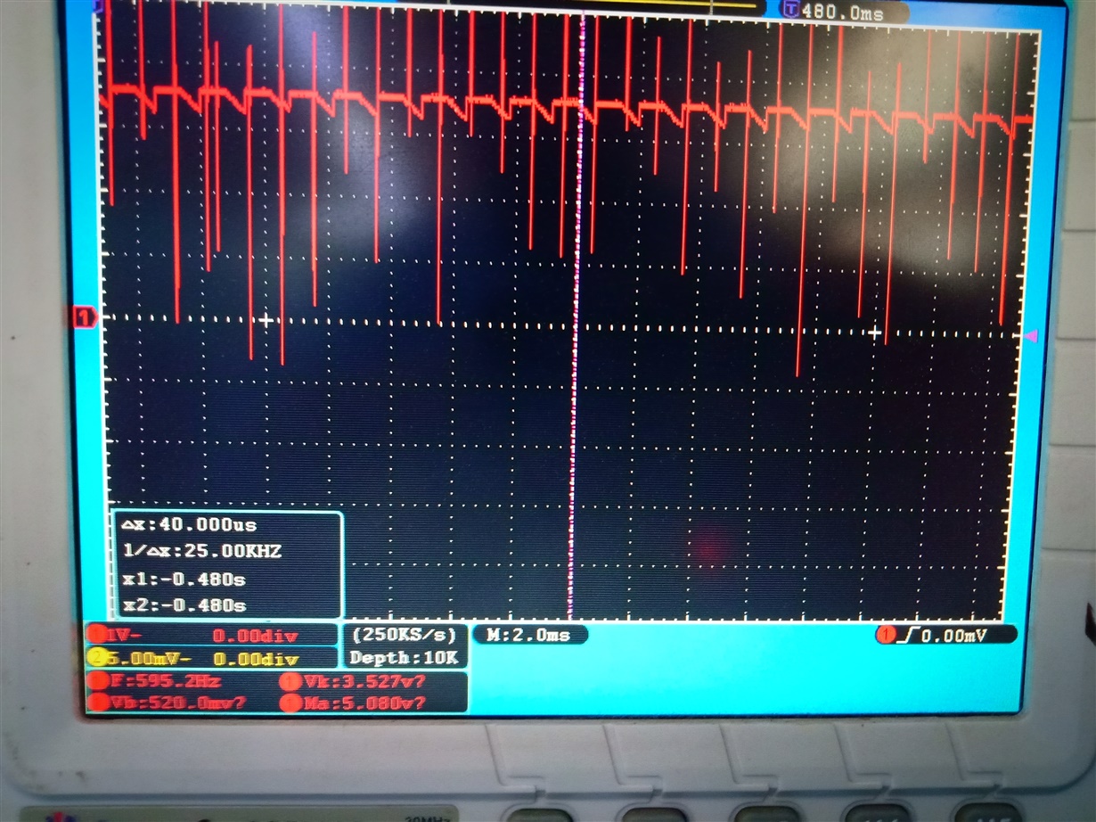
    Can you measure the PHASE waveform to make sure the converter works? Please also measure the voltage drop crossing charging current sensing resistor R21 with Vbat=3V and Vbat=3.8? It is unlikely but please make sure all correct component value.
  • Hi ezhao,

    I measured the PH waveform and attached a pic, please check the same.

    I tried to measure the Rsense (R21) voltage: Both at 3v & 3.8v of battery pack voltage corresponding V(R21)=0V;

    Cross verified with the component values seems to be all assembled well as per schematic!

    Thanks!,

    Regards

    Sagar

  • Sagar,

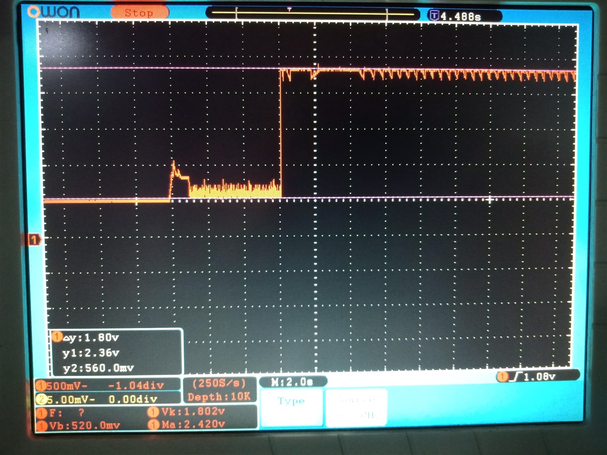
    When the battery is not connected, could you please take the FB pin output waveform and compare with the diagram below on the d/s?

    Thanks,

    Ning.

    Please click "This Resolved my issue" button if this post answer your question.

  • Hi,

    Sorry for the delay in response!

    I tried probing the point (VFB),

    I've attached a snap of the waveform, please find the same.

    Condition was: Charger On - Battery connected


    Thanks!

  • Sagar,

    Your measurement of PH on Oct 3, 2018 showed the converter did not switching correctly as the DC value without the spike is only 3.5V. Some component could be damaged. You want check the voltage of gate, drain and source of Q3.