This thread has been locked.

If you have a related question, please click the "Ask a related question" button in the top right corner. The newly created question will be automatically linked to this question.

UCC27537: why UCC27537 has big leakage current when device is still in off mode? how to use it in auxiliary power supply?

Part Number: UCC27537
Other Parts Discussed in Thread: UCC27533

Hi,

as below figure, when VDD is 7V, UCC27537 is till in off mode, but the IDD current is 300uA max current, what cause this high current?

in most case, UCC27537 is powered by auxiliary power, which has enough current capacity.

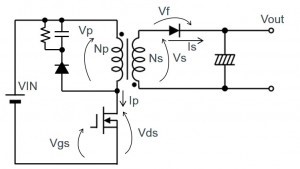
but now, one customer use UCC27537 in flyback auxiliary power supply, to drive flyback primary low side IGBT.

at startup, the flyback IC and driver UCC27537 is powered by pre-charge resistor, the pre-charge current is small, IDDoff current will make flyback IC has no enough VDD voltage to turn on.

question: 

1. what cause this high current inside UCC27537?

2. this test is at VDD 7V, if VDD voltage is 3V or lower, is this current smaller?

3. are there some methods to solve this problem?

  • Hi Max,

    Thank you for inquiring about our driver, my name is Mamadou Diallo and I will help address your concerns.

    This current is specified by design and 300uA is just the absolute max or corner case. In reality, it is typically less than that as specified by the typical value.

    Can elaborate why you would need the quiescent current at 3V Vdd? This current would not vary by much at 3V, I would expect very variation across that supply range.

    For this application, due to the charge resistor current, a device with lower Iq might be more appropriate then.

    If quiescent current is the main concern for the customer, I can help recommend alternate parts with lower quiescent current depending on other key care-about from the customer.

    UCC27524 UCC27517A and UCC27511 are devices with lower Iq however they do have lower supply range Vdd at 18V.

    Please let us know if you further assistance or press the green button if this helped address your concern.

    Thanks.

    Regards,

    -Mamadou

  • Hi Mamadu,

    thanks for your recommendation.

    but this driver is used to drive SiC, VDD at 18V is too low for this application.

    customer and i test his circuit at lab, but we find a strange thing.

    from UCC27537 block, the EN pin is internally pulled up to VDD. so when this part is used, EN pin can be floating.

    but from test waveform, when EN pin is floating, this device doesn't work.

    CH3: VDD voltage; CH1: UCC27537 IN+; CH4: UCC27537 OUT; UCC27537 EN pin is floating

    from below waveform, when the VDD voltage is charged to flyback IC turn on threshold by charging resistor connected with AC voltage, the driver send out PWM signal, although VDD voltage is higher than UCC27537 turn on threshhold, but UCC27537 has no output PWM signal.

    so flyback output voltage is 0V, the feedback loop make flyback IC enlarge its duty to 100%, and VDD capacitor voltage drops, when VDD voltage drops to flyback IC turn off threshold, flyback IC turns off. and then next start up cycle starts.

    then when use a 10k resistor to connect EN pin to VDD. the VDD current of UCC27537 increase a lot, this current makes the flyback IC can't start up, so we decrease charging resistor value to 300k, the total solution works. but this charging current is too large customer can't accept.

    now customer has 2 questions:

    1. why UCC27537 needs external pull up resistor to work? but it already has internal pull up resistor.  

    2.why when EN pin is connected to VDD with 10k resistor, the VDD current increase a lot?

    i also recommend UCC27533 to customer, because it has no EN pin, and IN- needs to  connect to GND, and IN+ is connected with input PWM.

    when customer get the sample next week, i will check with customer for UCC27533 and update to you the test result.

  • Hi Max,

    Thanks for providing the waveforms.

    Could you please share complete schematics? If NDA restricted, please email so I can take a closer look.

    This device is specified at 10V to 32V depending on FET driven. 18V is only nominal so it is OK to increase VDD within that specified range.

    Also just to clarify, when the EN is left floating, it is internally pulled up to Vref=5.8V through pull up resistor 500kohms as mentioned in datasheet, so it is not internally pulled up to VDD. But I agree it seems strange behavior when EN pin is floating.

    "then when use a 10k resistor to connect EN pin to VDD. the VDD current of UCC27537 increase a lot, this current makes the flyback IC can't start up, so we decrease charging resistor value to 300k, the total solution works. but this charging current is too large customer can't accept"

    How much was this current when connecting 10K resistor to VDD?

    For question #1, I have not seen this issues with other customers. Was this on one unit? or multiple?

    Just so i am understanding correctly, both question 1 and 2 are occurring when there is no switching?? am i correct?

    I will order some sample parts and test on my bench here to see next week.

    Thanks for recommending an alternate part while we continue looking into root cause.

    Thanks.

    Regards,

    -Mamadou

  • Hi Mamadou,

    For question #1, I have not seen this issues with other customers. Was this on one unit? or multiple?

    test 1 device. so i have asked sales to apply samples for customer to test more UCC27537. they will be arrived next week and i will do test with customer.

    Just so i am understanding correctly, both question 1 and 2 are occurring when there is no switching?? am i correct?

    yes.

    so i check the current only of UCC27537. remove other devices from board.

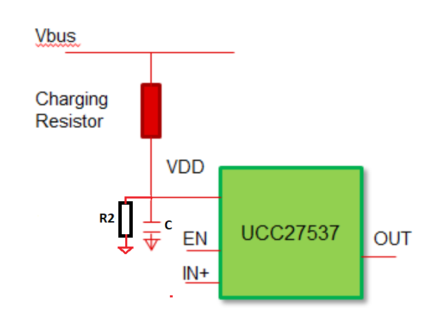
  • this is the test circuit.

  • this is the test circuit

  • Hi Max,

    I am looking into this, I will get back to you soon.

    Thanks.

    Regards,

    -Mamadou
  • Hi Max,

    This part is likely damaged. As currently configured, the device cannot withstand the high bus voltage (600V) the customer is applying the RC circuit, this driver is rated for 35V. 

    From my bench characterization, I get similar results as yours when the device is operated within the recommended operated limits. Anything above 35V damaged the driver based on your test circuit.

    But when within specified ranges, The current is still below the specified Idd current in the datasheet.

    Charging Resistor Vbus  VDD Current uA
    600000 10 1.56 14.06
    600000 20 1.935 30.1
    600000 30 2.191 46.3
    600000 35 2.277 54.5
    600000 40 2.344 62.76
    600000 50 2.486 79.19


    Consider adding resistor in parallel with the capacitor to form a voltage divider where R2 = 66kohms or below. I chose this value assuming max Vbus = 350V. 

    Please let me know if you require further assistance or press the green button if this helped address your concerns.

    Thanks.

    Regards,

    -Mamadou