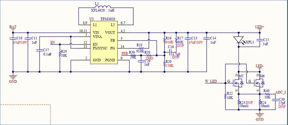
TPS63020DSJR VSON14功能异常导致,烦请原厂分析IC 功能不良的原因。
不良类型1: 2pcs,不良现象:各pin之间短路,具体为L1/VIN/PGND 之间短路;(TPS63020DSJR PIN L1,VIN,PGND are short)
不良类型2: 1pcs,不良现象:低电压输出时,电流大于1A。(When the voltage is low,the output current is over 1A )
This thread has been locked.
If you have a related question, please click the "Ask a related question" button in the top right corner. The newly created question will be automatically linked to this question.
TPS63020DSJR VSON14功能异常导致,烦请原厂分析IC 功能不良的原因。
不良类型1: 2pcs,不良现象:各pin之间短路,具体为L1/VIN/PGND 之间短路;(TPS63020DSJR PIN L1,VIN,PGND are short)
不良类型2: 1pcs,不良现象:低电压输出时,电流大于1A。(When the voltage is low,the output current is over 1A )
Part Number: TPS63020
Actually we had a Cap with over 33uF as the output capacitor, here are the real one we use for this case. But anyway, the capacity will not be the reason that let TPS630020 short-circuit.
For the questions from you, here are the feedback from my side:
1) Yes, we check our PCB, there are no short-circuit issue in PCB itself;
2) Yes, we using a new TPS63020 on the PCBA, it works well;
3) We have reverse input protection on the other side in the circuit;
4) We using 1x18650 Li-ion from Sanyo with 3200mAh(Max 4.25V), with protection unit,
5) For ESD or EOS, I think our factory have a good protection about this case, you can check our factory if you need.
Thanks for your additional note, we using MCU to make LED working under constant control, maybe the Peak current is not so well as the constant driver IC, but already hit our test target, the current control works well and stable.
Hello Dragon,
You mentioned that the problem is happening in production. Is it correct that you did not observe the damage issue during your system testing before going into production?
If this is the case, I think you should use the official device return path from TI, see here: 
In general any electronic part can be damaged on the input side by overvoltage or negative voltage. This could for example happen when the battery is inserted via bouncing of the different signals or if there was already charge on some notes which now add to the battery voltage.
Another common issue that we observed is long wires used in production causing overvoltage on input nodes because if the power supply used for testing is already turned on and long wires are connected to it, the connection to the device under test can cause high voltage ringing as wires are inductive.
In addition, you seem to have something attached to the FB node which might have some influence on the stability of the circuit.
In the typical application we recommend a 1.5uH inductor and 3*22uF capacitors. As you are using a smaller inductor and capacitor, it is possible that your load causes instability in the system. If a converter is instable on the output, it is drawing an instable current from the input which could cause oscillation.
Please check as well the current capability of the used inductor to make sure that it is not going into saturation.
But all these ideas need to be checked in your production setup to find a possible root cause for the damage.