This thread has been locked.

If you have a related question, please click the "Ask a related question" button in the top right corner. The newly created question will be automatically linked to this question.

LM431: Need Shunt voltage Regulation in our device

Part Number: LM431
Other Parts Discussed in Thread: TL431LI

Hi TI Team,

We are currently working in one of the project where we need to use shunt voltage regulation. We want to regulate the voltage at 5.7V. The maximum input current can be upto 1.5A

Can we use LM431 to achieve this?

  • Hi Navendu,

    Is all of the 1.5A going to the shunt voltage reference?
    What is the worst case current through the shunt?

    The LM431 can only sink 100mA which is far from 1.5A.
    In the situation that you do need to shunt 1.5A then a configuration like figure 19 with an appropriate transistor can handle 1.5A. This is more transistor dependent than LM431.

    Another alternative will be figure 30 from the TL431LI datasheet. In this configuration the shunted current wont always be on.
    www.ti.com/.../tl431li.pdf

    -Marcoo
  • Hi Marcoo,

    Thanks for your reply.

    We are planning to implement the circuit as shown in Fig.20 of LM431 datasheet. The fuse that we wish to use will be 1.5A. We will be using either transistor or thyristor to implement the crowbar circuit. Placing series resistor on the volatge line will create additional volatge drop(Fig 19).
    So I think the crowbar is the best way to implement this. In case of overvoltage transistor/thyristor will turn on and due to this the fuse will blow and circuit will get protected from Overvoltage condition. We dont want to restore the circuit to normal condition after overvoltage since the device is intended to be used in mining location so safety is the main concern.
    For regulation of 5.7V the value for R1 and R2 we have choosen 1.28K and 1K.
    The resistor between Voltage line and LM431 depends on the the biasing we need to provide?

    Let me know your views in this. If needed we can have more discussion on this.

    Thanks,
    Navendu
  • Hi Navendu,

    I can help you out with this question. How much do you expect your load current to be? If it is less than 100mA, than a crowbar circuit is not necessary. The R_bias resistor will be the current limiting factor (resistor between voltage line and LM431). This resistor is also used to bias the LM431. Make sure to provide at least 1mA to the LM431. The resistor depends on your input voltage and load current. Equation 1 on the datasheet can help you determine how to calculate this resistor.

    If it greater than 100mA, than the crowbar circuit is fine. Most crowbar implementations I have seen uses a thyristor over a transistor. Just make sure that the crowbar is implemented when the LM431 will expect currents greater than 100mA. Note that even at input current greater than 100mA , if the load is on and the difference between the input current and load current is less than 100 mA (I_IN - I_LOAD < 100 mA), than the crowbar does not need to be on.

    Hope this helps,
    Ethan
  • Hi Ethan,

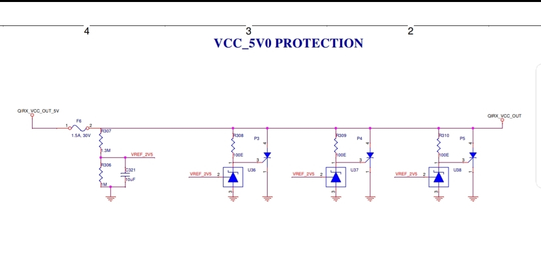
    The max load current will be 1.5A. I am attaching the schematic snippet. Please let me know if it is ok or not.
    We need to use three crowbar circuit so can we use a single reference voltage divider for all the three circuit.
    Let me know your comment on this.

    Thanks,
    Navendu
  • We are protecting the circuit at 5.7V.

  • Hi Navendu,

    I am a little confused on why there are three crowbar circuits. Can you explain to me the application again. I may misunderstood something and the crowbar circuit may not be the best solution. Is the LM431 used to regulate to 5.7V? What is the input voltage? Is the load sensitive such that it needs to protected at over voltage/current?

    The crowbar circuit is used an over-voltage protection such that in these conditions the crowbar is implemented (short) and the fuse is blown.Your current circuit wont work, because the SCR will always be conducting. You will need to use a triac (like figure 20) or a PNP transistor (figure 19).

    I have sent you a friend request on E2E so you can message me through email in case of sensitive information.

    Thanks,
    Ethan