This thread has been locked.

If you have a related question, please click the "Ask a related question" button in the top right corner. The newly created question will be automatically linked to this question.

TPS92602-Q1: Low PWM dimming duty cycle on time doesn't consistent

Part Number: TPS92602-Q1

Hi :

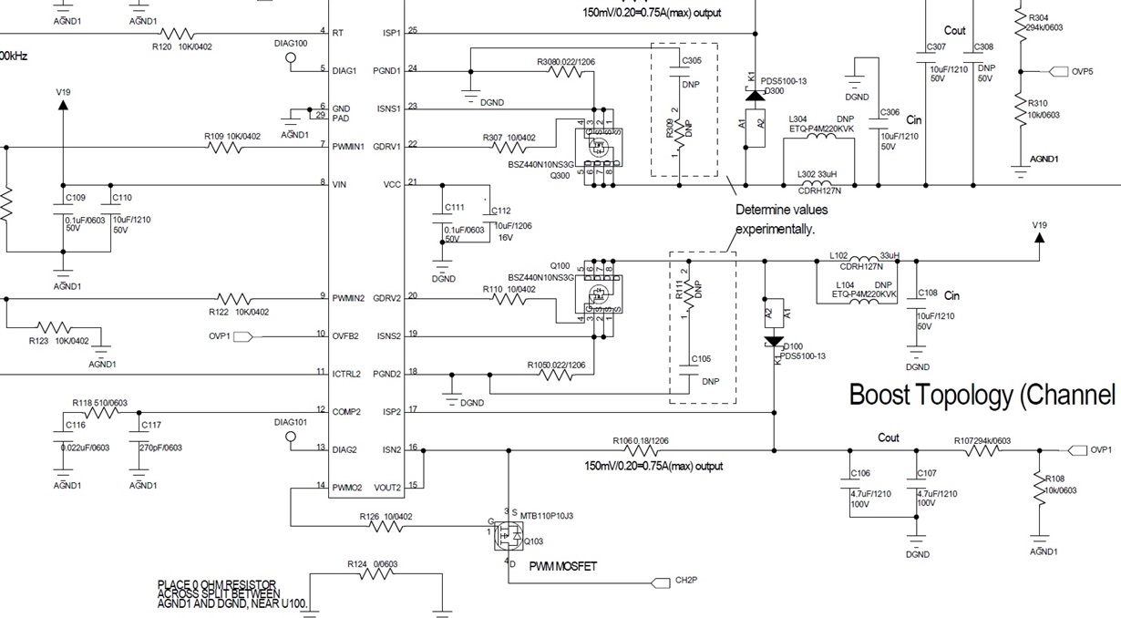
I am using TPS92602 boot topology to drive 15 LEDs. Because one of my PCBA board can not achive my lux requirement so I analyze this board and found something strange.

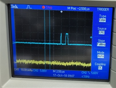
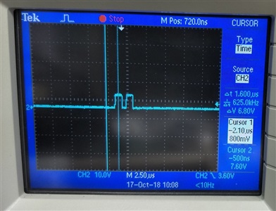
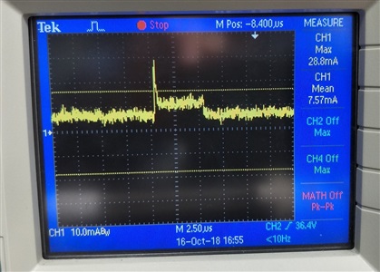
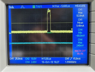
Figure 1 is good board GDRV2 waveform,Figure 2 is bad board GDRV2 waveform ,duty time is very different. This different duty time cause different LED current. Figure 3  is good board LED current when PWM dimming and Figure 4 is bad board LED current. Bad board LED current peak is higher but time is narrow. When I increase PWM dimming duty, the peak current value will decrease but good board peak current change a little when I increase PWM dimming duty. I want to all my boards behavior like Figure1. 

ICTRL2 voltage is 32.7mV

DC/DC PWM frequency is 600KHz external

PWM dimming frequency is 2KHz

PWM dimming duty in below figure is 1/200. 

Vin is 19V

Figure 1

Figure 2 

Figure 3

Figure 4

Figure 5 schematic

  • Hi Janson,

    If the PWM duty cycle is 1/200 as you said, the PWM on time should be 2.5us. It seems the on time in figure 4 is 2.5us, while the on time is figure 3 is 5us. Which figure is the good one?
    We have not seen any similar issue before. Have you tried placing another device on the "bad" PCBA board to see if it can work normally?
  • Hi Shirley :

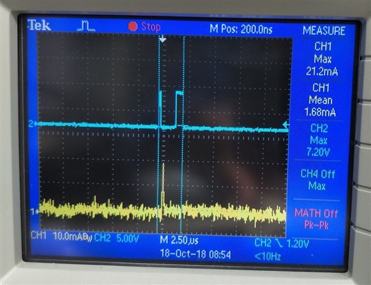
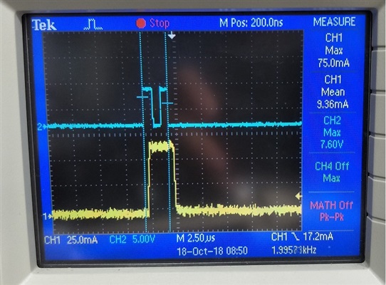
    I update figure as below. Figure 1 is good board and Figure 2 is bad board. Blue line is signal of GDRV2 and yellow line is LED current. I have changed LED of good one to bad one but the phenomenon is the same.

    Do you mean may I change TPS92602 of bad one to see if it can work normally?

    Figure 1. Good board LED current and pin GDRV2

    Figure 2. Bad board LED current and pin GDRV2

  • Hi,

    Since your switching frequency is 600kHz, and the LED PWM on time is only 1/2000/200=2.5us. There's only 1.5 cycles in each PWM dimming cycle. It is possible that you may get different waveform in each PWM dimming cycle. What is your required PWM dimming ratio? It's hard for the device to get a 1/200 PWM dimming ratio with 2kHz PWM dimming frequency. You can try a lower PWM dimming frequency, like 200Hz.
  • Hi Shirley :

    I slow down PWM dimming frequency to 500Hz but this issue still happen. After I change TPS92602 to new one, this problem solved. I still don't know what cause this problem.

    Best regards
    Janson
  • Hi Janson,

    Can you show the waveform of the bad part when the PWM dimming frequency is 500Hz? Did you see only one part having this issue?

  • Hi Shirley :

    I didn't record the current waveform but the waveform is similar as I attached before. I encounter one unit until now. I will keep watching if any other one happen.

    Best regards
    Janson
  • Hi Janson,

    Sorry I am still not clear what the problem is with this device. If the PWM frequency is 500Hz and the duty cycle is 1/200, you should see 6 switching cycles is one PWM cycle, right? It's better if you can share the waveform, so that I can try to analysis what is wrong with this device.
  • Hi Janson,

    I'll close this thread due to inactivity. If you have more questions, just reply to it directly and it will open again. Thanks a lot.