This thread has been locked.

If you have a related question, please click the "Ask a related question" button in the top right corner. The newly created question will be automatically linked to this question.

BQ34Z100-G1: BQ34Z100-G1 Custom Calibration routine

Part Number: BQ34Z100-G1
Other Parts Discussed in Thread: BQSTUDIO

Hi,

I'm looking to calibrate the bq34z100-g1 (voltage, current, temperature) using a python script for production use.

I've used Battery Management Studio to calibrate the voltage, and viewed the generated i2c commands, but I'm not making sense of it.

Can you explain the process or Is there documentation for this?

Thanks,

Andy

  • Hi Andy,

    In production, many customers will utilize bqStudio to calibrate 10-30 boards and then average those values to create a golden master image. Assuming a low variance, that golden master image may then be used to program all of the boards in production, without calibration.

    For using a python script, please create this golden master image and then export the BQFS or DFFS file from bqStudio. The BQFS (if you want firmware and data flash) or DFFS (if you want to speed up programming and just program data flash, assuming the firmware version on your device is the same) are already formatted i2c commands and are very easy to parse and program.

    For an example in ANSI C, please refer to the gauge communication app note, found here: www.ti.com/.../slua801

    Sincerely,
    Bryan Kahler
  • Thanks Bryan,

    I already have a routine to parse and program the golden file (.bqfs, or .dffs) over I2C.

    After this, It seems to me that each device will need to be calibrated individually to be accurate.

    For this reason, I was asked to also create a script to assist with calibration of the voltage readings etc.

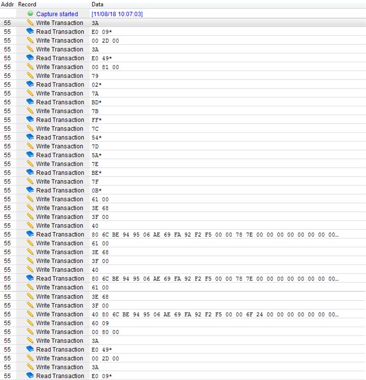
    Below is the I2C data for an example to calibrate the voltage reading, where for this case, the voltage guage reading is displaying 23124mV, and I then set the applied voltage to 21330mV in Battery Management Studio:

    I need to understand this so I can duplicate this for a general case where a user will enter a new (actual) voltage that might differ from the displayed voltage.

    The routine seems to be reading the Calibration class and changing the  voltage divider data at offset 14/15, which sort of makes sense, but there are other things going on here that I don't understand.

    Your help is appreciated,

    Andy

  • Hi Andy,

    If there is a large variance or unacceptable variance in voltage divider, resulting in an improper voltage reading, please modify the voltage divider value to calibrate voltage. Modify voltage divider until the reported voltage matches the actual measured voltage.

    Sincerely,
    Bryan Kahler
  • The I2C calibration routine I posted above, from the Battery Management Studio seems to do the following:

    1. Enable Cal mode

    2. Enter Cal mode

    3. Read Reserved command 0x79 through 0x7F.
    (Two of these bytes seem to indicate the voltage reading, but I can't be sure since they are not documented.)

    4. Generate the new voltage divider calibration value.
    I believe they use data from the reserved register, along with the "Applied Voltage" value to generate a new voltage divider calibration factor.

    I can't figure out how for example, they generate a voltage divider calibration value of 28424 when reading a voltage of 21294mV with the Applied Voltage of 21300mV.

    Any help would be appreciated.

  • Hi Andy,

    The manager of the tools and firmware teams has been notified, a timeline on response has not yet been provided, but I will update this thread by EOD Thursday at the latest.

    Sincerely,
    Bryan Kahler
  • That's great Bryan,

    I have the routine complete with the exception of the actual computation of the new divider value.

    I also added the steps that follow the update, which write the new checksum and exit and disable cal mode.

  • Hi Andy,

    Good news, this analysis should be complete by EOD Tuesday or earlier - still working on the allowance to disclose hidden values/parameters. Worst case, I will provide an update by EOD Tuesday.

    Sincerely,
    Bryan Kahler

  • That's great Bryan,

    I will also need this for the temperature and current calibration functions.

    Thanks!

  • Hi Andy,

    With the upcoming holiday, some issues have been pushed out - still working with the tools team and management to provide you with an answer. We may not be able to get a response until Monday, after the holiday. Hopefully tomorrow.

    Sincerely,
    Bryan Kahler
  • Hi Andy,

    Due to the volume from the holiday, the team is still working on that response. Will have an update by EOD Thursday.

    Sincerely,
    Bryan Kahler
  • That's fine Bryan,

    Please also find out if the Data Type "F4" shown for Calibration values CC Gain, and CC Delta are IEEE 754 Single Precision format.

    The reason I'm asking is that my golden file shows CC Gain as 1.246mOhm, but the value in the CC Gain Register is: 0x806CBE94

    This is a floating point of -9.9866E-39 if using  IEEE 754.

    I would expect 1.246 mOhm to be represented as: 0x3F9F7CEE

    Thanks,

    Andy

  • Hi Bryan,

    Any progress on this?

    Thanks,

    Andy

  • Hi Andy,

    I apologize for the delay - have been able to break the logjam on this issue:

    Voltage offset is not a separate value when performing calibration with the bq34z100-g1 and bqStudio. The voltage divider parameter is used to calibrate, more as a gain.

    Then, make sure to toggle cal_enable and enter_cal

    Then, we will need to determine the rawVoltage. To do so, use commands:

    0x7C - rawVoltageLSB
    0x7D - rawVoltageMSB

    rawVoltage = (rawVoltageMSB << 8) + rawVoltageMSB

    Next, measure the actualVoltage of the battery with a multimeter.

    Then, calculate calibratedVoltageDivider:

    calibratedVoltageDivider = actualVoltage * voltageDivider / rawVoltage

    Round calibratedVoltageDivider to an unsigned 16 bit value and write the value to Voltage Divider in dataflash.

    Finally, exit_cal and toggle cal_enable


    With respect to Xemics F4 data conversion, please refer to this post: e2e.ti.com/.../2020286

    If you have any other questions, please let me know.

    Sincerely,
    Bryan Kahler
  • Looks good,

    Thanks Bryan!