This thread has been locked.

If you have a related question, please click the "Ask a related question" button in the top right corner. The newly created question will be automatically linked to this question.

LMR16006: Part won't start at expected #SHDN voltage threshold

Part Number: LMR16006

Hello all,

We have a LMR16006X circuit that was sent back to me for review, for the first 3 test boards won't start. This is a known device for us, we have some 8 different products using that part, the schematic is based on Webench and board layout was submitted here before, approved and follows all the guidelines.

I'm at a loss here, for I can't figure it out. The switcher should be enabled by a resistor divider (an exact solution that works with other boards we made before), to turn it on when #SHDN gets above 1.25V. At 1.35V it still won't start. Here are some details if someone can help:

FIRST, SOME MEASUREMENTS ON THE PCB PADS WITHOUT THE IC:

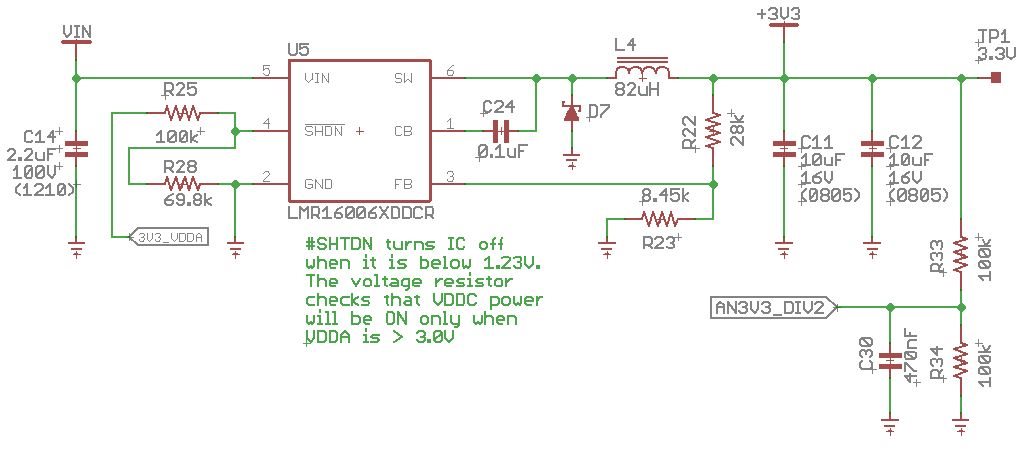
- #SHDN is behind a 100K/69.8K resistor divider, to prevent IC to starting before we get ~3.0V of an external 3.3V circuit. That is properly calculated for 3.0 * 0.411 = 1.23V, and we are correctly reading 1.35V into pin#4 
- VIN is set at 12.0V
- All other pins read 0V (GND, FB, CB and SW).
- No noticeable shorts anywhere on the load side of the board, caps good, resistors good.

Now, when soldering the IC (fresh IC right out of the tape, marking D02X):

- #SHDN raises: instead of the expected 1.35V, it becomes 1.55V (AS IF SOMETHING INSIDE THE IC IS BRINGING THIS VOLTAGE UP)
- Output voltage (SW) is 1.72V (should have been 3.3V, adjusted by the 28K/8.45K FB divider).
- VIN remains at 12.0V
- FB Reads 0.4V (correct division of wrong output voltage 1.72V * 0.232)

SW output signal is a ~635Hz quick pulse that outputs VIN during ~500ns, a if "not able to start"... (I can capture a scope if useful)

NOTE: If I increase #SHDN voltage a bit higher, by pulling it up (via 2K2 resistor) from an external 3V or from 12V VIN feed, part works properly!

Is there any chance of a bad IC batch, or any similar known occurrence? We tried LMR16006X's from two different shipments, although both are from the same vendor and bought in a short time from each other... Three full boards were tested and failed, and I'm now working on a board with the very minimum components to check the issue, tried 3 switchers already with identical results.

Any help or guidance for further tests are really appreciated!

Regards

Bruno

  • Hi Bruno,

    I forwarded this to the product expert.

    Regards,
    Tim
  • Hi Tim,

    Thanks, and I'm looking forward for a feedback from the colleague!

    Further info: I fished another part from a working leftover board and soldered into this PCB - that part was purchased from same vendor some 5 months ago. - and the behavior is exactly the same.

    I though of soldering one of these "suspicious" parts into a different known-to-be-working board, but unfortunately we don't have any available which would use the enabling resistor divider... The one I stole the old part from uses #SHDN directly pulled up to VIN.

    (Schematic added on the next post)

    Regards

    Bruno

  • By the way, a schematic is worth 10,000 words, so here it is:

    Bruno

  • Hello Bruno,

    Thank you for your detailed description of the problem and sharing the schematic.

    I calculate 1.36V at the input of the SHDN pin. Does this match your expectation as well? One thing to note is tha thte maximum rising threshold for the SHDN pin is 1.38V. You will want to be above 1.38V at SHDN pin so that the tolerance of resistors cannot effect this performance as well.

    When you say that three boards did not start up, did you have a number of boards start up as expected? If possible, you could swap a 'working' IC with the ones that are performing not as expected to see if this fixes the problem.

    Would you also be able to share a waveform of the VIN, SHDN, SW and Vout when you are turning on the device?

    Best Regards,
    Katelyn
  • Hi Katelyn,

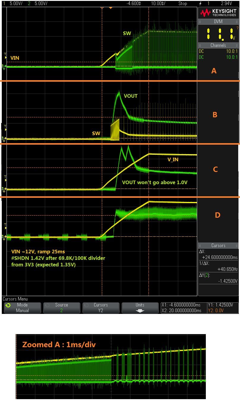
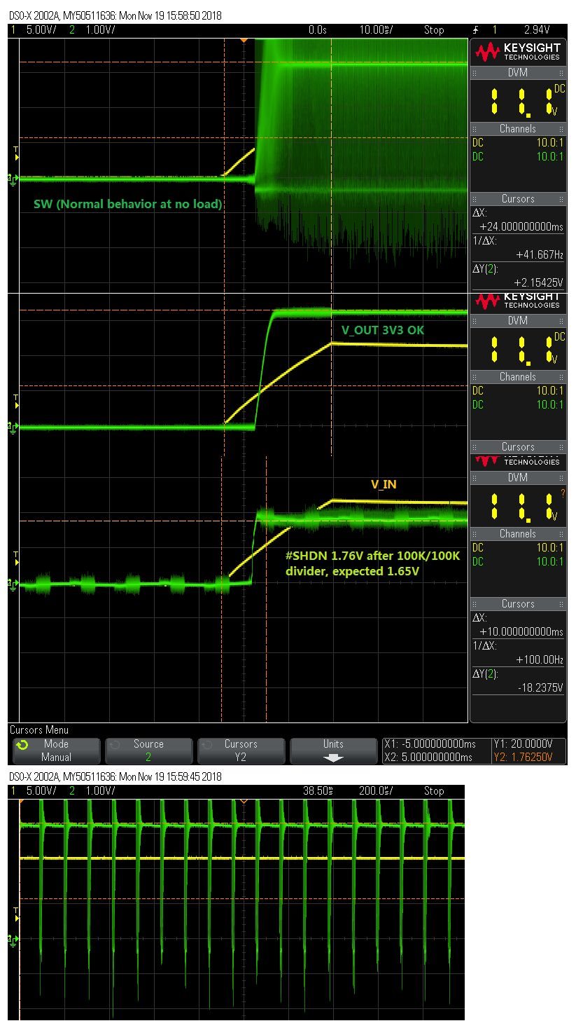
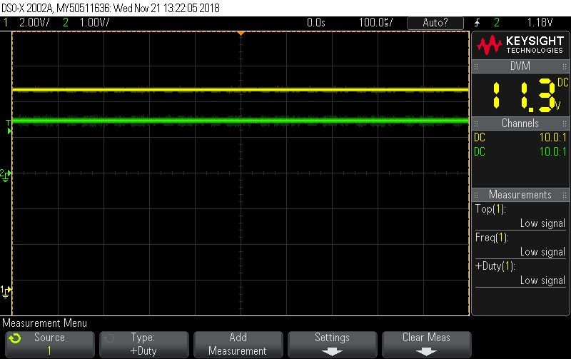
    The scope I have available is only 2-ch, so I had to make some image stitching. You will find attached the waves captured from two boards:

    - One board is populated with 69.8K/100.0K divider as per the project. This would rise voltage to 1.35V (worth saying that, while your mentioning of resistors tolerance makes sense and have been taken in account, the threshold enabling voltage for this part is described at 1.25V, so it should be fine at 1.35V). One mysterious thing here is the voltage actually showing ~1.42V, higher than the theory but still not enabling the switcher. Another interesting point to be repeated: voltage here WITHOUT the IC on the board is correct at 1.35V.

    - The other board is populated with 100K/100K bridge, just for the sake of testing. Expected voltage would be 1.65V, measured voltage is again higher, at ~1.76V. This condition is enough to enable the switcher, and we have the expected output voltage.

    To your other question, when said that three boards did not start up, that's as far as we tried (actually, we built four now). We do not have any working board on this design.

    Hope this will provide the info you need, and let me know if I can help any further!

    All the best,

    Bruno

  • Hi Bruno,

    Thank you for sharing the detailed schematic.

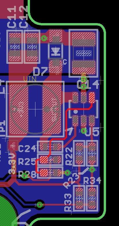
    It looks as though the SHDN voltage is noisy.  Is it possible this is sitting to close to the threshold or there is another signal coupling to the SHDN which is interfering? Would you be able to share the layout as well?

    I tried the same test on the EVM, and I tried powering up the device by forcing a voltage on SHDN.  This one device turned normally at 1.2V.

    Also, when I said that the shutdown voltage should be at least 1.38V, I was referring the maximum voltage from the EC tabel in the datasheet.

    Best Regards,

    Katelyn

  • Hello Katelyn,

    Thanks for the attention and guidance!

    While I wasn't expecting noise on the #SHDN signal (counting on the "far end" capacitor only), maybe the lack of a nearby cap and the fact that it routes both underneath the CB cap and the IC itself are interfering... There is nothing else connected to that line other than VDDA for a TM4C123 microcontroller.

    It is probably a good idea to add a nearby cap, below R28, and also route the #SHDN trace on the opposite layer towards pin #4...

    For now, to enable testing the rest of the board, I'll try to leave a 100K/100K bridge to keep it ON until the next board spin. Also, thanks for pointing out the "exception" on the threshold voltage for #SHDN, we did fail to take that into consideration.

    Any other suggestions are most welcome.

    Regards,

  • Hi,

    Yes, using the higher resistances or tying SHDN directly to VIN will eliminate this problem for now.

    I think adding a high frequency bypass cap in parallel with R28 is a good idea. This would be a good test to run to see if it effectively cleans up the SHDN signal.

    Also, you are correct that you want to route the SHDN signal away from the SW area/trace.

    I would also recommend adding a ground plane to the top layer of the PCB. This will also decrease noise as the return path for all signals will decrease.

    Best Regards,
    Katelyn
  • Hi Katelyn,

    The cap in parallel provided amazing results, I couldn't hope for better!

    Ugly but working:

    Thanks for all the support!

    Regards

    Bruno