This thread has been locked.

If you have a related question, please click the "Ask a related question" button in the top right corner. The newly created question will be automatically linked to this question.

UCC25600: wide range output

Part Number: UCC25600
Other Parts Discussed in Thread: UCC28019A, TL431, UCC28951, UCC28950, UCC2895, UCC28951-Q1, UCC28950-Q1, PMP2187, LM5035, TL494, UCC21520, UCC2818

Dear All,

i selected the UCC25600 for a 400 W resonant converter.

the problem is that i need to adjust the output voltage of a resonant converter when it works.

the output voltage has a wide range from 0 to 400 V.

the input voltage is 400 V ( form UCC28019A PFC stage ).

the maximum current is 1 A and the load is a  resistance ( variable resistance 400 W ).

please see the bellow schematics ( form data sheet ):

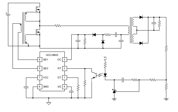
can i adjust the voltage by change the Vs?

or can i adjust the voltage by changing the upper resistance in the divider?

or is there any other methods to do that?

Regards,

Ras

  • Ras

    To adjust the output voltage of UCC25600, the reference voltage out the outer voltage loop needs to be adjusted. In the typical schematic the reference is set by the TL431, which has an internal voltage reference. In order to turn this fixed reference to a variable voltage the feedback needs to be modified. A common implementation technique is to use an op amp as the following app note shows www.ti.com/.../slva662.pdf. Note that the Vref in Figure 1 of this app note is the control voltage that will determine what the output voltage will be.

    I'd like to highlight that the performance of UCC25600 will be very limited with such a wide output voltage range. Resonant LLC converters generally do not work well with wide input or output voltage ranges, so a large range of 400V will be very challenging to meet and will have limited performance. A Phase Shift Full Bridge with UCC28951 would be a better topology to use since it does not have the same voltage range limitation. You can adjust the output voltage of this controller/topology using the same scheme that's described earlier.

    Best Regards,
    Eric
  • Hi Eric Faraci,

    thank you for the explanation.

    i have two problems:

    1) in the case of UCC25600, in the PMP5967 reference design, the input/output voltage ratio is approximately 32 ( ie 380/12 ). the performance of the design seems high.

    2) in your answer, do you consider adjusting output voltage, when converter works or in the develop stage?

    Regards,

    Ras

  • Ras

    To answer your questions

    1. Since the resonant LLC topology has a transformer, the input to output voltage range is not an issue since the turns ratio can enable any ratio desired. The issue is when the input voltage range or output voltage range is wide. The following two PSDS papers provide more details about this and LLC operation www.ti.com/.../slup263.pdf and www.ti.com/.../slup306.pdf.

    2. This can adjust the output voltage when the converter is operating.

    Best Regards,
    Eric
  • Dear Eric Faraci,
    thank you very much.
    would you please explain the differences between UCC2895, UCC28950, UCC28951?


    Best Regards, Ras
  • Hello Ras

    The UCC2895, UCC28950 and UCC28951 are Phase Shift Full Bridge controllers.

    The UCC2895 does not have SR control outputs and is mainly intended for use on the primary side of the isolation barrier.

    The UCC28950 and UCC28951 do have SR control outputs so if you they are the better choice if you want to use SRs in your design. But, even if you are going to use diode retification th They also offer easier synchronisation than the UCC2855 and include a better control in burst mode. They are also easier to use in Peak Current Mode control than the UCC2895 - they have a dedicated pin to select Voltage Mode control or Current Mode control. they have been designed to be used as secondary side controllers but have been successfully used as primary side controllers.

    The UCC28951 will operate better at wide duty cycles while in current limit than the UCC28950 and is normally the better choice

    Hope this helps - please re-post with if you have any more questions.

    Regards
    Colin
  • Dear Colin Gillmor,
    thank you for that useful and valuable information.
    can you guide me how can i gather/receive this information of a product as genetal? for example how can i understand that UCC28951 will operate better at wide duty cycles.

    Bets Regards, Ras
  • Dear Eric Faraci,
    please verify if i think true;
    it is not possible to adjust voltage for UCC2813 as for UCC28950 since the error amplifier of UCC2813 is internal.

    best Regards,
    Ras
  • Hello Ras

    The application note linked in the UCC28951 datasheet shows how to choose between the UCC28951-Q1 and UCC28950-Q1 devices. The note is valid for the UCC28950 / UCC28951 devices too. You can find it at www.ti.com/.../slua853.pdf

    In general, I would suggest that you use the UCC28951.

    Regards
    Colin
  • Ras

    For your question on UCC2813, the internal error amplifier and reference can be bypassed. PMP2187 (schematic: www.ti.com/.../slur196.pdf) is a good example of it configured with an external error amplifier and reference. The same techniques discussed earlier can be used to adjust the voltage.

    Best Regards,
    Eric
  • Dear Eric Faraci,
    thank you for the reply.
    is there a design procedure/guide for the technique?

    Best Regards,
    Ras
  • Ras

    The following training video should help you with the feedback compensation design

    training.ti.com/power-tips-compensating-isolated-power-supplies

    Best Regards,
    Eric
  • Hi Colin,
    it brings up for me another question.
    the duty cycle is adjusted from 0 to 100% to vary output voltage in full range.
    is the feedback output linear with the full range variation of output voltage?

    Best Regards,
    Ras
  • also consider the temperature dependency of the optocoupler.
    is my talk true ( this post and previous )?


    if it is true, there are four solutions in general ( to eliminate transistor output optocoupler ):
    1) non isolated power supply
    2) using high linearity optocouplers or isolation amplifiers.
    3) primary side regulation.
    4) secondary side controller.

    what do you think about these?

    Best Regards,
    Ras

  • Hello Ras

    If you need to change the output voltage from 0V to 400V then the LLC is the wrong topology to use. The reason is that the input to output voltage conversion ratio of the LLC depends on the switching frequency - typically a 3:1 change in switching frequency will give you about a 2:1 variation in output voltage - take a look at the curves on page 16 of the UCC25600 DS for some examples. A 400:1 ratio is not possible - irrespective of the controller you use.

    There are some advanced techniques which will extend this conversion ratio by modulating the duty cycle as well as the frequency but you still won't get to the range you want.

    Your application is for a 400W converter running off a 400V DC bus. In this case the best solution would be a PWM stage running at a fixed frequency. The topology could one of several but here are the ones I would consider.
    1/ Half-Bridge using for example a LM5035, you will have to use external High/Low side drivers with this part to cope with the 400V input
    2/ Hard Switched Full Bridge using a TL494, again, external High/Low side drives will be needed
    3/ Phase Shifted Full Bridge (PSFB) using UCC28951, external High/Low side drivers will be needed


    When operating off a 400V dc input one would normally use a zero voltage switching topology like the PSFB and if your output voltage was always going to be high then the PSFB could maintain ZVS over most of the power range - down to about 20% of load or maybe less with careful design but in your case the output power will go down to zero so it's more important that the power stage function over the entire power range than maintaining low switching losses. What I'm suggesting is that in your case maintaining ZVS isn't a key consideration and the increased switching losses can be compensated by switching at a lower frequency.
    This means that you sould consider a hard switched topology running at a relatively low frequency - maybe about 35kHz as well as a PSFB.


    1) non isolated power supply - easiest if you don't need an isolation barrier:cg -
    2) using high linearity optocouplers or isolation amplifiers. - both of these will work but will be expensive:cg
    3) primary side regulation. - Works well for some topologies - used a lot for low power flybacks but Vo accuracy is never going to be very good. Could be used on a Buck derived converter like the Half Bridge, Full Bridge or PSFB but accuracy will be worse than in the flyback case.:cg
    4) secondary side controller. - Works really well, you will need a small auxilliary supply to get the controller running during the start-up phase - and you will have to use isolated gate drivers like the UCC21520: cg

    It is possible to use 'ordinary' photo-transistor opto-couplers to form part of an isolated feedback path providing you understand the device degradation mechanism and how it compares to the expected PSU lifetime.


    Regards
    Colin
  • Hello Colin,
    thank you very much for this complete explanation. several of my questions are answered.

    two problems with ordinary optocouplers remain:
    1) is the output of the optocoupler linear form 0 to 100% of the output voltage?
    2) should i worry about temperature dependency? if yes, what can i do for?

    Best Regards,
    Ras
  • Hello Ras

    The UCC2813 uses an internal reference and compares VREF/2 to the FB signal so by adjusting the scaling of the FB signal you can achieve any duty cycle you need to keep the output voltage in regulation. The main problem is that the UCC2818 has only a single output signal which is not enough to control the two switches in a half bridge or the four switches in a full bridge (at least not without significant external steering logic). Honestly - I would not consider it further for your application.

    The UCC28950 and TL494 both have internal error amplifiers and references.

    There is a lot of training material on the PSFB at https://training.ti.com/ a quick search on 'Phase Shifted Full Bridge' gives
    training.ti.com/.../products

    There is also several useful articles from the Power Supply Design Seminars series at www.ti.com/.../login.shtml - the 'Select Topic' drop down menu has selections for half bridge, full bridge (including PSFB )

    Regards
    Colin
    Please note that I will be out of the office on Christmas Holidays from Close of Business on 21st until 7th Jan
  • Hello Colin,
    thank you for the reply.
    apparently there is a wrong here.

    i would like to start a new post with controller of a hard switching topology.

    Best Regards,
    Ras
  • Hello Ras

    That's fine - please open a new post when you have a question and we'll do our best to answer it. In the meanwhile, I'm going to close this post.

    Please note I'm going to be away until 7th Jan for Christmas Holidays.

    Regards

    Colin