This thread has been locked.

If you have a related question, please click the "Ask a related question" button in the top right corner. The newly created question will be automatically linked to this question.

BQ25713: How to fully power down the charger?

Part Number: BQ25713

Hello.

In my design, the battery will work as a backup to sustain device functioning for a while in case of mains fault. Equipement is powered off either by the operator or when battery is fully depleted. Once powered off, the equipment will be powered back on only when mains voltage is normal.

Could one of the configurations below work? The idea is that the microcontroller pulls down ILIM_HIZ to switch the power supply/charger off. The main idea is to reduce current drained from battery, especially when it reached the minimum charge.

If the above does not work, is there a simple way to achieve the same functionality?

  • Hey Elder,

    I do not believe either of these configurations will work. In the normal single P-Ch BATFET configuration, the PFET is turned off by setting the BATDRV voltage to the VSYS voltage. However, there you will potentially have VSYS totally isolated from SRN (battery), likely resulting in a weak pull down of on of the FETs, possibly turning it on.

    You may also have trouble turning on the FETs if the operator decides to do this.

    And in reality, we have not evaluated an implementation like this which means we cannot assume other normal charging operation will be okay.

    I think a better implementation is using a controllable load switch on VSYS to isolate your system from the charger when you want this low leakage state.


    Regards,
    Joel H
  • Hello, Joel.

    I was thinking about this matter after I posted and I suspected the scheme might not work. I understand the P-MOSFET works in the linear range under some circumstances so the one I added would be biased backwards.

    One alternative I considered was placing the P-MOSFET like the second schematics above (Q5) but driving its gate with a N-MOSFET which the gate would be pulled down so that the microcontroller would have to apply a high logic level to turn the P-MOSFET on. Thus, when I wanted to shut-down, I would set the uC output as input and put it to sleep so that its VCC would eventually go to zero. So, only when mains is back the microcontroller would turn on and the charger/supply would be started up in an orderly way.

    I am also considering the load switch too. There are some advantages in terms of flexibility and simplicity (it is more straightforward than the scheme above). The problem is that the quiescent current of the switches/controllers I looked at are relatively high, 0.5mA. My concern is when the battery reaches minimum charge and the circuit continues to drain it to a point it might be damaged if kept in storage for too long. So, before I follow this path, I would like to explore alternatives where the quiescent current is much lower.

    BR

    Elder.

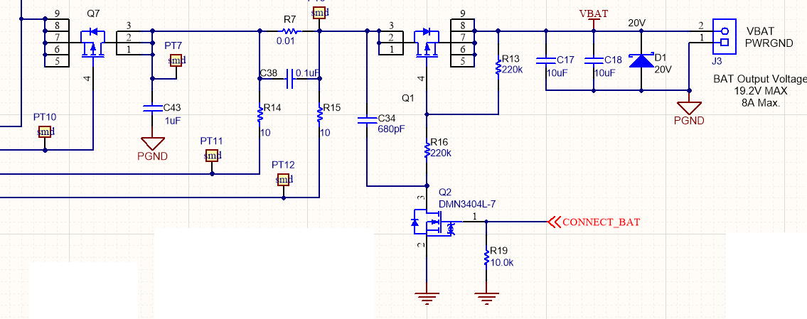
  • They say a picture is worth a thousand words, so... That's what I meant. Could this work?

  • Hey Elder,

    I believe this could work, but again since have not tested this configuration I cannot say for sure. In fairness, the second half of the circuit here with the added switch is reminiscent of standard battery pack protection circuitry, namely the discharge FET. So in theory this works.

    My only concerns are the the resistor sizes here on Q1 may only partially disable the FET as they are both 220k AND more importantly that the CONNECT_BAT signal needs to be active high to keep the FET off. The question for my latter concern is whether this can be done on your MCU when you've lost power to SYS.


    Regards,
    Joel H
  • Hi, Joel.

    I am glad to know this scheme might work.

    I think when CONNECT_BAT  is high, the power FET (Q1 in the last schematic) is enabled instead of disabled. My idea is the microcontroller to change the pin to input (so that CONNECT_BAT goes to zero) and immediately put itself to sleep so the FET keeps disabled when uC's VCC shuts down.

    The 220k resistors make VGS = -5V (VBAT = 10V). I have to double check to see if this voltage is sufficient for Q1 to fully conduct.

    After giving further thought to your  previous comments, I am looking at a more conservative approach, with a load switch as you suggested. If I may find a way to keep quiescent current very low, I will follow this path, which is more consistent with the tried design.

    BR

    Elder.

  • You are correct. The VGS would be half of the battery voltage.

    And it could be tough to find a lower IQ load switch has several of them have some internal charge pump that can sink a bit of current to keep their FETs on.


    Regards,
    Joel H
  • Hi Joel.

    I will try to figure a way out to use the load switch as it has some advantages such as overload protection. Otherwise I will try the scheme above. It is good to know that it is at least viable as a solution.

    Thank you very much for your support.

    BR.

    Elder.