Other Parts Discussed in Thread: CC1310, , TPS63000
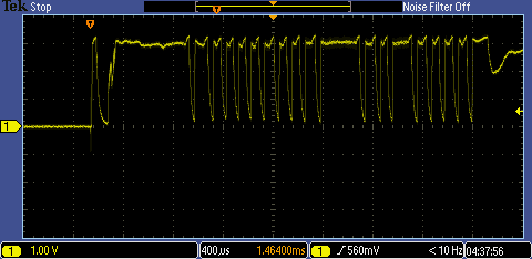
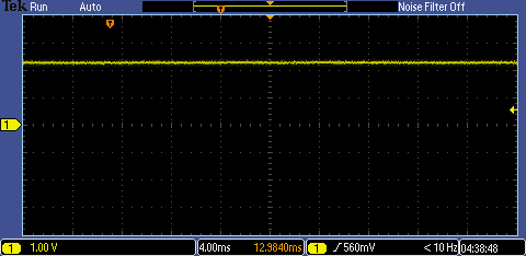
I am seeing strange behavior with a batch of TPS63001 regulators. The PCB consists of a TI CC1310, some other low-power sensors, and the TPS63001. The board will eventually be powered from a Li battery, but right now is being powered from a bench supply. Expected max current 15mA during radio TX, quiescent current should be about 2mA (largely due to a power LED that is on for debugging).
Of the first batch of eight boards, 4 of the TPS63001 regulators were foo'ed: on the first power-up, they started drawing 200mA with nothing else powered on. Using the radio, the current would jump to 215mA, but it would never go much below 200mA. Using a FLIR, the failed regulators were red hot (over 150C). The other 4 units functioned as expected. There were no shorts present on the 4 defective boards, so I replaced the 4 regulators, thinking maybe they were defective. They functioned exactly as expected. When we were done testing, we had 8 working boards. They all took programs, and they all ran through their initial tests.
I've been running sensor calibrations with two of the units, and noted that the quiescent power started increasing, slowly at first. Starting two days ago, the baseline power was 5mA with peaks to 20mA during radio TX, then by the afternoon it climbed to 40mA (and 55mA peaks), and after running through the night, yesterday morning it was 100mA (115mA peaks), and by the afternoon was up at 150mA (165mA peaks), and the regulator was getting hot. I didn't want to leave it unattended after that.
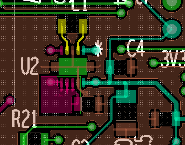
The board is relatively simple, there are three power rails - the supply rail from the battery (presently using a bench supply), the always on 3.3V regulated line, and an auxiliary line that is enabled by the MCU to turn on the sensors and is tied to the 3.3V regulated line. I have test points on the board that allow me to directly drive the 3.3V regulated line with a bench supply and by-pass the regulator. The quiescent power draw of the rest of the circuit is exactly as expected - 15mA peaks, 2mA for the LED when everything is asleep.
The regulator design is based on a WEBBENCH output, but I had to make some part substitutions due to availability. The filter caps for the regulator are all rated to 50V (input voltage would never go above 4V), input is 10uF, output is a series of 3 at 10uF, 47uF, and 100uF. The 10 and 47uF are placed nearly adjacent to the regulator, while the 100uF is placed between the regulator and the CC1310. The inductor 2.2uH is rated to 20V and 500mA and is nearly adjacent to the regulator.
There are other temperature sensitive components on the board, so we used lower temperature solder paste that reflowed at 220C, so I don't think we cooked anything. I'm not really sure where to begin...