This thread has been locked.

If you have a related question, please click the "Ask a related question" button in the top right corner. The newly created question will be automatically linked to this question.

UCC29910AEVM-730: UCC29910AEVM-730

Part Number: UCC29910AEVM-730

I have bought the UCC29910AEVM-730  experimental board.When I testify it as the instructions in the user 's guide, the output voltage is zero.And I notice that at the begining, the electronic load current should be set at 0.2A.I don't why the board will go to the protect mode.

  • Hello Shi

    TI EVMs are of course tested before being shipped so the EVM should have worked when it arrived to you.

    There are a few things I would like you to check:

    Please check that the fuse is not blown

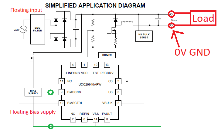
    Please check that the outputs of the electronic load are floating. The EVM generates an 84V output BUT this is NOT referenced to the same ground as the 10V Bias supply. If the Load and Bias supply share the same ground then the power stage will not operate. If you are unsure, you can simply disconnect the load completely and use a floating DVM (handheld DVM) to measure the output voltage.

    Please check that the 10V Ext Bias is present across C23 - just in case D1 has been damaged

    Make sure S1 is in the ON position (I'm sure you have checked this but I include it for completeness)

    Startup should be ok into any AC voltage (50Hz/60Hz) greater than 85V RMS - I'd suggest you use 120Vac until the power stage is running.

    If these steps don't work then you should contact the TI source where you purchased the EVM and ask them for a replacement.

    Please let me know how you get on -

    Regards

    Colin

  • Thank you so much , I'll try it.
  • Please let us know how you get on - I'd be interested to know.
    Regards
    Colin
  • Thank you so much.I have tried and when I didn't connect the electronic load, the output voltage was 86V. However, I want to know how to use the electronic load correctly. I mean how to connect the electronic load with the output in order to make the load is floating. In that way, I can check the board operating efficiency as the output current varies. Thank you again!

  • Hello Qi

    It's good that the EVM appears to be working - 86V out at no-load is expected.

    The UCC29910A controls an inverted buck stage. This allows it to control a low side MOSFET for simplicity but it means that the output of the power stage does not use the same ground reference as the input. There are some things you could try -

    1/ The best solution would be to use a Load with a floating input.

    2/ Another solution would be to use resistors as the load - although

    3/ Use a floating AC input (a 50Hz isolation transformer between the AC source and the input terminals of the EVM.) Then use a floating DC bias supply. You could then connect an electronic load to the output of the PFC stage and use the 0V output as the ground reference for the system. If you do that then ALL the system voltages will be referred to the GND output marked in the diagram and this is the point you would have to use for your 'scope grounds. This would work but you would need to be VERY careful not to accidentally use the wrong ground reference for any of the measurement instruments and I'd avoid this approach if at all possible.

    Regards

    Colin

  • Thank you, I'll try it quickly.

  • Hello Collin, in today's test, when I tested the EVM without load, at the beginning, the board made a sound. I don't know the reasons. And the output voltage becomes zero. What's the problem? Thank you.
  • Hello Qi

    I'd suspect that the EVM is damaged, I'd check the input fuse and the resistor R19. You could try replacing the Fuse with a new one with the same rating. If R19 is open then I'd suggest you get in contact with TI and order a new EVM.

    The main problem with this EVM is that the output is high side referenced - so that the 84V output is offset from the input ground by Vin-84V - . This has the advantage that the power stage uses a low side MOSFET which is easy to drive. The Buck PFC has some advantages over the more usual Boost PFC - especially its efficiency versus line - this topology is discussed in the article at www.ti.com/.../slup264.pdf

    Regards
    C olin
  • Hello Colin,

    I check the devices, there is no damage. So, I want to know,in this case that the output is 0 and the EVM make a sound, what part in the EVM

    had damaged? Possible mistakes I made during the test process. Thank you!

  • Hello Colin,

    I have checked the EVM, the R32 is almost Mohm and I replaced the ZR2. But when I set all thing down, the fuse was broken. What  way can I do to recover the EVM?

    Thank you!

  • Hello Qi

    The resistor R32 is present to protect the output capacitors in the case of a failure of the power MOSFET. In this buck converter, if the main power MOSFET goes short circuit the full input voltage is applied to the output. This generates a current pulse in the R32 which then goes open circuit, the output capacitors are rated to 100V.

    The simplest solution would be to return the broken EVM for a replacement - I'm not sure of the rules around this process.

    If  you want to repair the EVM then you will need to replace R32 - DO NOT simply put a shorting wire across it because a wire won't fuse open if the power MOSFET goes short circuit.

    The next thing to do is to disconnect the controller from the power train by disconnecting R21. Then use a 0/10V signal generator to put a 100kHz square wave on the gate of the power MOSFET Q5. Then slowly increase the input voltage to the EVM from 0V up to about 20V or so. The duty cycle at the MOSFET is 50% so you should see Vin/2 at the output. This will allow you to check that the power stage is ok. Then replace R21 and remove Q4.

    Connect a 10V rail to the driver IC and the signal generator to the input to the driver IC. Then re-check operation at 20Vin. If it looks ok you can then increase Vin until Vout is at 84V - probably about 170V or so at the input will do this. You should check the efficiency of the stage to make sure it is reasonable and that nothing is getting too hot.

    Then, check that the controller is getting the correct inputs at its VBLK, LNSNS, BOTH CS pins. Check VREFIN = 1.5V and VCC = 3.3V . Check the signals at each of the pins according to the descriptions in the data sheet.

    Regards
    Colin

  • Hello Qi

    R32 and ZR2 are protection components and will operate if the output voltage exceeds about 100V or so. When ZR2 activates it will open the fuse too.

    You should replace the fuse and check the switching MOSFET, Q5 and the diode D6 are still ok.

    Tthen proceed with some debug as follows.

    Remove R21. and SLOWLY apply an AC voltage to the input of the EVM - increase this voltage up to about 120VRMS. the output voltage should remain at 0V (remember, Vo is referenced to the high side rail)

    Remove the AC voltage. Put a 'scope probe on the output of U2 (NOT TP10 because R21 is removed) and on the VDD pin of U3 (TP7) and then follow the steps in section 6.1 of the EVM user guide. VDD should be at 3.3V. The burst of pulses may not last very long because the power stage is disconnected and there is no bias being generated by the power stage but you should see some activity for a few ms. Check the switching frequency of the pulses and their amplitude.

    If you don't see pulses then repeat the test while monitoring the DRV output of the controller (TP5) and the input to the driver at Pin3 of U2.

    Check the REF pin is at 3V, if it's not then D8 may be damaged.

    If that doesn't work then please let me know.

    Going through a repair process like this can be a good learning experience but please don't forget the option of simply obtaining a new EVM -

    regards
    Colin

  • Hello Colin

    First , thanks for your replays, and I have bought a new one . Some issues I get confused about are below.

    1. Things went well when a 300ohm resistance as the load was connected to the TP13 and TP12 until  I put a oscilloprobe on each side of the load. The R32 broken down again. I don't know what is the problem? How to correctly measure the wave of the output voltage?

    2. In terms of three types of "ground', respectively of the input ,the output and the 10V-bias ,what are the differences among them? 

    3. When I used a 100ohm resistance as load ,the output voltage is 0. Later ,I noticed that on conditional of electronic load, start up with load current greaterthan 0.2A mag trigger over current protection and may make output voltage in hiccup operation. How can I make the output power up to 100W at the beginning? 

  • Hello Qi

    I'm glad that the new EVM worked with a 300 Ohm load.

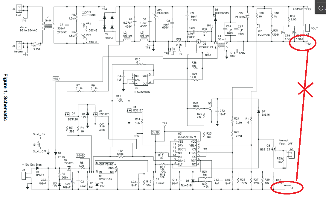
    The UCC29910 circuit is a buck PFC and is different to the more usual Boost PFC because its output voltage is NOT referenced to the input 0V. You can see that the positive output of the power stage is connected to the positive side of the bridge rectifier and the negative output is kept at 84V negative of the positive output. The controller ground is at the negative terminal of the bias supply which is NOT the same potential as the negative output of the buck stage. For proper operation, the input AC, the Bias supply AND the load must all be floating. If you have one 'scope probe on the negative of the bias rail and another 'scope ground on the negative of the output then you will form a short circuit from -Vout at TP12 to ground at TP3 (bias supply -ve) and the current will opencircuit R32.

    If you want to measure Vout, then you can use a floating DVM or use two 'scope channels, one for Vout_pos and the other for Vout_neg, using TP3 as the ground reference for both.

    if R32 has gone open circuit, then you will probably find that ZR2 has gone short circuit too. The input fuse may have open circuited too (F1).

    My suggestion is to replace these components and then try some of the diagnostics tests I sent you earlier.

    DO NOT place a short circuit across R32 - the resistor is there to prevent serious damage to the output capacitors C19,C20 including preventing them from venting.

    Please keep me informed

    Regards

    Coliln

    https://e2e.ti.com/cfs-file/__key/communityserver-discussions-components-files/196/4657.Untitled.png

  • Hello Coliln

    If I want to get the full load at the begining, and I cannot use the electronic load. Directly, I use a 70ohm resistor. It doesn't work. What should I do? More even, if the EVM's output is connected to another voltage module which requires 100W. How to connect them and  to guanrentee the PFC output is 100W at the beginning?

    Thank you!

    Regards

    Qi

  • Hello Qi

    The EVM should be able to support a 70 Ohm load - can you re-try with a lower load - 60 Ohms or so.
    Please check that the FAULT pin is at > 2.5V.

    I'd also suggest that you check that the other pins on the IC are at the expected voltage -
    REF at 3V
    VDD at 3.3V
    VBLK = 0V until startup then at 1.048V when VBULK = 84V
    CS = CS = 0V until current flows
    LSNS = 264mV RMS or greater
    457mV < BSNS < 913mV

    If the EVM starts, then its 84V output is available as an input to a downstream DC/DC converter -

    Please let me know how you get on.
    Regards
    Colin
  • Hello Colin

    Today I have two questions,

    1. I connected the electronic load with the beginning current 0.2A, first , the EVM made a sound,and then when I measured the ouput voltage with multimeter, it turned out to be 0V and the electronic load operated in the protection mode. Should I start the constant mode to lower than 0.2A?

    2.About the 70 ohm resistor, I mean that I connected it directly to the output . The supposed current is 1.2A when it starts. But the output voltage is zero. How to achieve the full load at the beginning? I guess the EVM output current should vary from the 0.2A to 1.2A  rather directly be up to 1.2A? What changes can we do to achieve that goal?

  • Hello Qi

    You are correct, you should start the EVM into a load of less than 0.2A and then increase the load once the output voltage is present. In most system applications the PFC stage will start into zero load or a very light load because the down-stream DC/DC converter will not start until its input voltage is established.

    Regards
    Colin
  • Hello Colin

    Everything goes well. But, there are two problems I have to figure out.

    1. How to testify the operation efficiency of the EVM? As for Pin, a multimeter measuring the valid value of the input voltage, a hauer device sensing the input current; as for pout, the format U2/R being used. Finally, the outcome is far away from the datas from the use's instruction. How  to get the varible current value of the input correctly?

    2. If the EVM is connected to a downstream voltage module, what are the potential mistakes I may make or some important issues I should pay attention to?

    Regards 

    Qishi

  • Hello Qishi

    If your downstream device is an isolated DC/DC converter then you can simply connect the 84V output from the EVM to the input of the DC/DC. This was the original intention of the buck PFC. You can see how this can be done in Fig 23 of the document at https://www.ti.com/seclit/ml/slup264/slup264.pdf

    Regarding efficiency measurements - The efficiency will be high so it is important to take accurate measurements. Given that you know the resistance accurately then you can simply measure the voltage across it. The input power is more difficult, we use wattmeters which accurately measure the real power into the converter - taking account of the fact that the current is non-sinusoidal and there may be a slight phase shift between input voltage and current due to X capacitors.

    The User Guide suggests using the power meters on the AC source - these may or may not be accurate enough for this application - it depends on the source's specification

    Regards
    Colin

  • Hello Qi

    My apologies for the delay in replying.

    R32 open means that something has caused an overvoltage on the output capacitors. The two most likely causes are that the load -Ve terminal connected the -Vout to the input ground (TP3 or TP6). The other possibility is that the MOSFET (Q5) has blown short circuit. In either case, it is possible that the current sense resistor R19 has gone short circuit.

    I'd suggest that you double check that your test set up does not cause a short circuit between TP12 and TP3 -

    Please let me know how you get on - I'll try to reply more quickly next time although I am travelling on business next week.

    Regards

    Colin

  • Hi Qi,

    Since there has been no further updates to this post for nearly two weeks I am going to close it. Please open a new post if you have more questions.

    Regards

    Peter
  • Hello Colin,

    Thank you for your reply. Recently, I have one problem.I have read that article you recommended me, but there is just a little information about the connection between the EVM and the downstream. I am not sure that if the output of the EVM is linked to the downstream converter, what will happen? Should  I take some rules or principles like the middlebrook rule into account the operation of connection? Could you share me some resources about the cascode of power converters? And, as for this specific EVM, are there any considerations during the process of connection? Thank you so much!

    Regrads

    Qi

  • Hello Qi

    I would suggest the following

    1/ Check that the MOSFET Q5 is not short circuit from drain to source. If it is then you should replace it.

    2/ Replace the input fuse F1 with a part with the same electrical ratings.

    3/ Replace R32 (do not short circuit R32 - it is needed to prevent an over voltage condition on C19,C20 if Q5 should go short circuit.

    4/ Remove R21 and short Q5 gate to source

    5/ Turn on the EVM in the normal way, be careful with the grounding - the EVM output at TP14 is not at 0V so the load must be floating - you will not get an output voltage but you should see gate drive pulses at pin 13 of U3 (DRV) and at pin 4 of U2 (OUT)

    If these pulses are present and ok then remove the short at Q5 and re-connect R21

    The EVM should run.

    Please let me know how you get on.

    Regards

    Colin

  • Thank you for your reply. Recently, I have one problem.I have read that article you recommended me, but there is just a little information about the connection between the EVM and the downstream. I am not sure that if the output of the EVM is linked to the downstream converter, what will happen? Should  I take some rules or principles like the middlebrook rule into account the operation of connection? Could you share me some resources about the cascode of power converters? And, as for this specific EVM, are there any considerations during the process of connection? Thank you so much!
  • Hello Qui

    The output of the EVM should be considered to be a simple, low output impedance voltage source which can be connected directly to the input of a downstream converter. The source (EVM) will work correctly given that the load (downstream PSU) does not overload the source. It is not necessary to use Middlebrook's extra element theorem to do this.
    The only thing to be careful about is that the + output of the UCC29910A EVM is connected directly to the positive line voltage with the - output of the EVM at -84V relative to the + output. This is why you must use a floating load while loading this EVM. Normally the output of a PFC stage is connected to the input of a DC/DC converter with an isolation barrier. The output of the DC/DC converter can then be grounded to any convenient point - or left floating.

    There is a series of blogs starting at e2e.ti.com/.../how-to-approach-a-power-supply-design-part-1 which you may find useful. The powerstage designer tool can also be a useful resource for you www.ti.com/.../powerstage-designer

    regards
    Colin
  • Hello Qi 

    We have moved this conversation to a new thread https://e2e.ti.com/support/power-management/f/196/p/780249/2980008?tisearch=e2e-sitesearch&keymatch=UCC29910*#2980008

    So I'm going to close this one.

    Regards
    Colin