This thread has been locked.

If you have a related question, please click the "Ask a related question" button in the top right corner. The newly created question will be automatically linked to this question.

BQ76940: Testing for REGOUT

Part Number: BQ76940

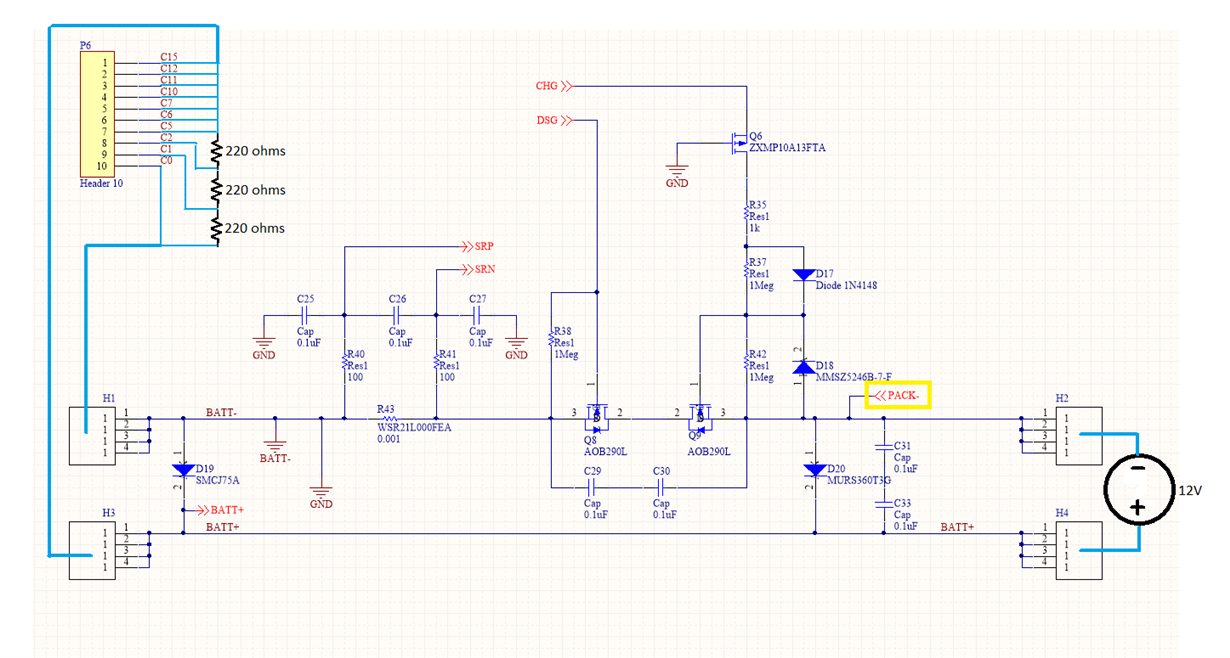
Good day, I built a BMS board in which I use the BQ76940 and a PIC24 as microcontroller. Here is the schematic (I used Altium): /cfs-file/__key/communityserver-discussions-components-files/196/0383.Schematic.rar

Is it possible to power up the board using a 12Vdc battery (instead of 36V, as I currently don't have a dc supply)? I just wanted to check if the BQ76940 REGOUT produces 3.3V which should power up my microcontroller. However, I do not get any voltage from REGOUT. Checking REGSRC also, I do not get any voltage. And so I thought maybe I need 36V for it to work.

Thanks,
Robert

  • Hi Robert,

    Yes and no to 12V.  You have a 9 cell design with the BQ76940, this would be 1.3V/cell if divided equally, but more importantly there would be only 4V/cell group which would be below the recommended VBAT for each group, and below the VPORA level.  REGSRC may be about 2V and insufficient to provide REGOUT.

    However if you short all cell inputs C5 and above together and divide the 12V across the remaining cells, you get 4V per cell and 12V for the bottom group.  This will allow the part to boot, REGSRC will be a couple volts below 12 and provide good power for REGOUT.  This will allow you to check power to your MCU and potentially develop code, but since there is no power to the top cell groups the BQ76940 will have a permanent XREADY fault which will prevent you from turning on FETs.

    Since you need REGSRC to have adequate voltage for the FET gates, you might look at alternative connections for REGSRC.  See the application note http://www.ti.com/lit/pdf/slua749 section on REGSRC.

  • Hi Robert,

    Another comment which may be obvious, when working with a new board it is always good to start with a current limited supply.  If you have a battery it would be good to provide some current limiting device at a lower value than the fusing you expect for your final product in case the circuit or assembly has some paths you did not plan.

  • Thanks for the reply! What I did was instead of Li-Ion batteries, I used 220ohm, 1/4w resistors.

    I tried shorting all cell inputs C5 and above , but I can't seem to get any voltage across the cell inputs. I probed BATT+ to PACK-, it showed 12.6V. However, probing BATT+ to BATT- shows 0V.

  • Hi Robert,

    It sounds like you have a connection from the battery to VSS but not to BATT-, with FETs off CHG will pull PACK- low.  This is odd since your schematic shows VSS connected to GND which connects to BATT-.  You might check that the connection is present.

    In your circuit, similar to the EVM you need to connect the battery negative to BATT- and C0, the EVM provided this with a dip switch.  The battery positive will connect to both BATT+ and C15.  Again with XREADY you will not be able to turn on FETs so BATT+ may not be needed now, you will know your circuit better.  In the limited voltage test situation C1 and C2 (At P6) connect to the  resistor divider.

  • WM5295 said:
    In your circuit, similar to the EVM you need to connect the battery negative to BATT- and C0, the EVM provided this with a dip switch.  The battery positive will connect to both BATT+ and C15.  Again with XREADY you will not be able to turn on FETs so BATT+ may not be needed now, you will know your circuit better.  In the limited voltage test situation C1 and C2 (At P6) connect to the  resistor divider.

    I'm positive this is what I did, maybe the problem really is in the FET not pulling PACK- low. I just checked the connections; VSS, GND, and BATT- are indeed connected. 

  • Weird, (using my 12V setup and only using 3 cells) when I probe BATT- to PACK-, it shows -12V. It should be 0, right?

  • Hi Robert,

    If BATT- is the negative of the meter, something sounds wrong.  Check for proper connections on the board and to other equipment.  

    If PACK- is the negative of the meter, it will depend on your load on PACK and the meter.  With 12V you will not be able to power all the cells, so you will get an XREADY fault and not be able to turn on FETs.  With the FETs off, CHG will pull down so it will try to pull down PACK- (to GND or BATT-), but the path typically has a high resistance.  The meter also has a high resistance.  Both those 2 are in parallel across the FETs.  If you have any resistive load between PACK+ and PACK- you get a voltage divider.  

  • Hi, thanks for the response!

    Can you please check my setup if there's anything wrong with it? I used http://www.ti.com/lit/df/tidr773/tidr773.pdf as reference.

    And 2 questions;
    (1) I just realized there is nothing connected to the PACK-(yellow box) anywhere in my schematic, as it was only used in bq78350, which I replaced with another MCU, PIC24. Should it be connected to another net?
    (2) Can you please tell me how the PACK- gets pulled down to GND (BATT-)?

  • Hi Robert,

    Thanks for the picture, this helps with understanding.

    The BQ76940 operates with power from the battery cells (BATT and C0 to C15).  When it is on and conditions are normal it can enable the output of the battery assembly, often known as PACK, however it is named H2 and H4 in your diagram.  To operate your board for initial test and software operation, connect the 12V from H1 to H3 rather than H2 to H4.  The 12V will then divide to provide 3 simulated cell voltages for the lower cell group of the BQ76940 and provide a current path to the H2 and H4 terminals. 

    1. PACK- should not need to go anywhere else if you are not measuring the PACK voltage.

    2. In this test setup, only the bottom group of cells will have power, so the BQ76940 will have a XREADY fault which can not be cleared.  This will prevent the MCU from setting the DSG bit, so Q8 will be off.  CHG has a load detect feature which pulls down on the CHG pin, see the data sheet.  The pull down will come through the Q6 body diode, R35, R37, and D18 to PACK-.  If you put a meter across the pack terminals you will measure a voltage, perhaps about 80% of the BATT voltage.

    Once you have a setup with all cells connected or simulated, XREADY can be cleared.  If the voltage is sufficient to avoid UV you can set the DSG_ON bit, it will output DSG high which will turn on Q8, PACK- will be pulled down through the body diode of Q9 if or until CHG is enabled and Q9 is turned on also.

  • Hi, thanks for clarifying! I now have voltages for the lower cell group.

    There may be something wrong with the output LDO of the AFE..  I measured REGSRC, it is around 10.77V. However, REGOUT is 0V

  • I'm now getting REGOUT, it is 2.48V (using 12V source and REGSRC of 10.77). Should I expect it to rise to 3.3V if I use a 36V source?

  • Hi Robert,

    The voltage of REGOUT is configured at the factory according to the ordered part number.  See the BQ76940 data sheet section 6 on page 4 for part options. It seems like you have a 2.5V option device but would prefer a 3.3V version.   The REGOUT voltage is regulated and should not change significantly with the REGSRC voltage (see VEXTLDO_LN Line regulation).  If you have a 3.3V output part check the load current to be sure it is not approaching the short circuit current and pulling down the voltage.

  • Thanks for the help! I think this REGOUT would be okay since the PIC24 Operating Voltage Range is 2.0V to 3.6V