This thread has been locked.

If you have a related question, please click the "Ask a related question" button in the top right corner. The newly created question will be automatically linked to this question.

TPS65131: TPS65131 Question about output voltage Ripple.

Part Number: TPS65131

Dear support member,

My customer used TPS65131.
I have a question.

(Question)
Only the negative side is used without using the positive side.
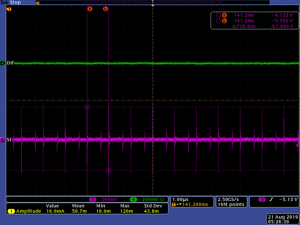
There is 1Vp-p noise on the minus 5V output.
Is there a solution?

A circuit diagram and waveform are attached.

TPS65131Question_190806.pdf

Best regard.
Bob Lee.

  • Hi,

    I have notified our expert regarding this topic. Please expect a response by 8/8/19.

    Thanks,

    Aaron

  • Dear Aaron Goodson,

    Thank you very much for reply.
    How is the progress?

    Best regard.
    Bob Lee.

  • Dear Aaron Goodson,

    How is the progress?
    When can you answer?

    My customer tried the following.

    (1) The feedforward capacitor has been adjusted.
    ⇒12pF → 4pF / 60pF / 83pF was changed.
    But output noise did not change.


    (2) RC snubber was inserted between OUTN and GND.
    ⇒I put 33Ω+1000pF.
    But output noise did not change.


    (3) A high frequency capacitor was inserted on the output side.
    ⇒ I put 10uF / 0.1uF / 0.033uF / 5600pF / 100pF.
    But output noise did not change.

    Are there any other measures?

    Best regard.
    Bob Lee.

  • Hi Bob,

    I don't think the issue is related to customer schematic.

    I'm suspecting the layout or partially damaged part.. It is more than one failure?

    What is the quiescent current ?

    Regards,

    Costin

  • Dear Costin Cazana,

    Thank you very much for reply.
    I have add a question about your answer.


    (Question1)
    Your answer is that "partially damaged part".
    Could you teach how to check "partially damaged part"?
    Which part should I check?


    (Question2)
    Your answer is that "quiescent current".
    My question didn't say "quiescent current".
    Where did I say "quiescent current"?

    Best regard.
    Bob Lee.

  • Dear Costin Cazana

    Thank you very much for reply.
    How is the progress?

    Best regard.
    Bob Lee.

  • Hi Bob,

    Schematic wise I see no issue, the negative output should be clean. The spikes in scope capture seems to be  the switching frequency.

     Recommended steps to debug the root cause of this noise:

    1) Quiescent current - my suggestion is to check this current to find out the device(tps65131) on the board  is not damaged. Very likely DC-DC converter is ok

    2) Measurement issue. The scope probe ground may be the issue. I probed the negative output with two probes. A singe ended passive probe with 2" ground( pink) and a differential active probe ( green ). Even if the diff probe has much wider bandwidth(200Mhz)  the output is clean. As expected  noise is bad when I'm adding short wire between diff probe negative input and board gnd. Both probes are set to DC with -5V offset. The load is ~150mA

    3) Board layout issue. Switching frequency may couple into the ground due to fast edges.

    Regards,

    Costin 

  • Dear Costin Cazana,

    Thank you very much for your answer and measurement waveform.

    I reply my customer your answer.
    I will feed back it.

    Best regard.
    Bob Lee.

  • Hi Bob,

    I'll close this thread, for new customer questions please start a new one

    Best Regards,

    Costin